2000 Through 2002 Activity Notes
Note: The wings are illustrated as reattached in the following drawings, but that hasn't been accomplished yet. However, the wings are now essentially in the illustrated position, except that the Left wing is about two meters lower vertically than the Left wing root for easier reassembly of the flight control surfaces. The detail illustration includes a note, now obsolete, stating that the tail has not yet been reattached. Ignore that note - the tail has been reattached to the aircraft.
Current Status Map Detail.jpg (1.14 MB)
Current Status Map Overview.jpg
(867 KB)
31 July 2002:
As is obvious, I've been completely derelict in keeping this page up to date. Sorry about that - time pressures have been overwhelming. And I'm not correcting this problem now, except to advise checking the new image links, because I've been adding notes to each set of new images (here for example), which have essentially replaced the notes here, except in more abbreviated form. This might turn out to be a permanent change in my method of reporting events and status, or might not - we'll see.
30 November 2001, v2:
Just some quick additional notes: I removed the attachment bolts from the valence light tunnel for a short distance and installed one of the new sidewall panels in place of the old original panel. It looks wonderful, so I've essentially decided that I'll move the valence light tunnel up enough to provide for the increased height of the new sidewall panels, so that I can replace all the old with the new, even though it will entail a modest amount of custom mounting work in order to relocate the valence light tunnel. I'll also have to move the oxygen conduit up a bit too. An additional advantage of the new sidewall panels is that the uncovered area between the top of the sidewall panels and the bottom of the ceiling panels will be significantly reduced, so that finishing of that area will be easier, and yield a nicer looking cabin. The new sidewall panels also extend down toward the floor further than the old original sidewall panels, which also improves aesthetics. The newer style plate that fills the space between the bottom of the sidewall panels and the floor may also provide a much more graceful means to mount domestic power receptacles (IEC-320 receptacles) than the old fill panels do. But the surfaces of those plates are covered with a lot of stubborn adhesive residue which was used to secure carpeting. I've pressure washed a couple of them, but it's tough and time consuming, and doesn't completely remove the residue. I'll have to find a better method - maybe an ionic solvent.
I'm still awaiting newer door liners and several other items from Aero Controls. I haven't been able to reach Aero Controls lately either by email or voice, so I don't know what the status of the items is. This is very frustrating.
Somehow a mouse got into the fuselage, an event that hammered my sense of pristine refuge from an unsavory side of country living. I don't know how this occurred, though one possibility is that I stupidly (and due to late day exhaustion) Left the air stair door open overnight after a pressure washing session late this fall. Perhaps the little fellow managed to scale the last air stair step into the cabin in search of new opportunities. It couldn't have been an easy feat due to the structure surrounding that last step, but mice can manage to clear some pretty substantial obstacles.
Here's the really crushing part of all this: Other than primates and, on very rare early occasions, my cat, there's never been anything larger than an insect in the cabin. All the material I've been laboring so hard to wash to a pristine condition was moved immediately into the cabin after washing in order to insure that it would stay clean. The first little black mouse dropping I noticed was on an object that I had washed only a day or two earlier. My heart sank, because I knew immediately that all that work to create a pristine refuge from rodent feces was gone. And as I perused the landscape, I noticed that the soiled items tended to be those I had most recently washed. It was almost as if the mouse was mocking my hard work. The more logical explanation though is that the poor guy was starving, and desperately searching every new item for food.
Shortly after the discovery, I revisited all the elements of the fuselage to try to determine how he gained access. I examined all the seals on the turbine bypass conduits, which were found fully intact, and the climate control conduits between the climate control bay and the heat exchanger area, and all the other possibilities. There was one small open conduit associated with the climate control bay - half of a small "Y" conduit wasn't sealed. But I couldn't find any chewed sealing material associated with the area. Maybe I somehow failed to seal it long ago when I sealed everything else. That doesn't seem likely though since the other half of the "Y", which is within a few inches of the unsealed side, and clearly visible, was properly sealed (with a thick section of dense closed cell foam, tightly packed). It's a mystery. In any event, I doubt that the mouse entered there, due to the conduit's shear vertical walls. And there were no droppings in or adjacent to the conduit that I could see. But of course I did correct the problem - the conduit is sealed now. In spite of this conduit discovery, I suspect that leaving the air stair door open overnight was the source of entry.
I placed a tender trap in the cabin adjacent to the most heavily soiled area, and check it daily. It's been several days, and I've found no new droppings, and the trap hasn't caught anyone. So I'm afraid the poor guy has probably succumbed to hunger and the cold. (I know what you're thinking: "No, there's an opening somewhere, and he just Left." But there isn't - the fuselage is genuinely sealed. And there's evidence in the form of partially eaten desiccated fly bodies that suggests that he's been very desperate for food.)
The challenge now is to fully locate all the sites he's visited, reclean the affected items (that will have to wait until next spring), and find the body. That last item could be really tough though. If he nested and subsequently died in insulation behind the cargo bay walls, I probably won't be able to detect him by smell, because it's cold in the unheated cabin, so decomposition will be slow. By the time spring arrives though his body will probably have dried and decayed enough that there won't be enough decomposition Left for me to smell even during the warm season. So it would take a trained dog or high tech sniffer of some kind to locate him. Maybe it won't come to that - if I'm lucky I'll find him as I go through the material to determine what has been soiled. If I'm not lucky, I've got a challenge on my hands. Ultimately I do want to replace those cargo bay walls with new material anyway...
21 November 2001:
Sorry again for the long delay in updating this page. I'm always swamped, and have been missing multiple obligations, including one for the county which I feel terrible about, even though in practical terms no harm seems to have been done. But I really need to get my show in order for them soon.
As I've mentioned, my tiny business experienced an unexpected surge in orders last summer, and as a result I was stuck in the lab during a major portion of the outdoor season, which was a real bummer. And I have three orders on the books now, so aircraft work is necessarily time shared.
To the nuts and bolts: I thoroughly pressure washed the wing tank areas on both sides of the right wing cut line. Those areas contained old debris Left over from the original salvage crew work and the move, including plant debris. But now those areas are beautifully clean. I then completed the bolting of the heavy splice beams to the outer portion of the right wing, and I found that I could work around the damaged right main gear strut for the purposes of reattaching the right wing by leaving the strut almost bottomed out and finessing the wing up and down with a hydraulic jack rather than using the strut to raise and lower the right side of the aircraft. That worked, and I pulled the right wing into the wing root to within less than a tenth of an inch of it's final position, almost ready to drill and set the inner twenty bolts. I couldn't quite get it fully lined up though - I've pulled it in the proper distance, and I can line up the bottom edges. But the top edges seem to harbor a small offset that I haven't yet overcome. There might be an internal hang-up associated with a small protrusion of some kind - I need to get inside and look at the area to check on that.
It still remains at that stage of construction, because I felt compelled to turn my attention to more pressure washing due to the waning warm season. And I did complete a lot of that. But now pressure washing is quite difficult due to the cold air and water, and the low sun position (which causes the trees to shade my solar heating rings completely even when the sun's at it's peak). But I am still doing some pressure washing on the better weather days.
I may return to the wing work shortly, though it depends upon the weather too, as a matter of safety. I don't want to lose control of a heavy object (the wing) by pushing my luck in difficult weather. But hopefully I'll complete the positioning and bolting soon. I may want to add some additional but smaller internal splice beams to the existing structure using some modest Sized aluminum stock I already have on hand. If the integrity after bolting the primary splices and whatever additional splices I add, but prior to welding, seems adequate, I'll remove the stacks of supporting railroad ties under the right wing. In the meantime, I've been referred to and have talked with a local fellow who's evidently a very good aluminum welder, and hope meet with him here later. I doubt that we'll be able to do any welding until next summer due to frequent wind this time of year, but at least we can set the stage so as to get out of the blocks quickly next year. Hopefully by that time I'll have the Left wing connected via the splice beams and thus ready to weld too.
The interior pressure washing isn't finished yet (boy that's been a big job), but certain areas are. Everything aft of the landing gear bay, including the rear cargo hold, the aft galley, and the two aft lavs, are completely finished. So is the cockpit and the forward galley. I couldn't quite finish the forward lav, which is a bit of a disappointment, only because it was a personal goal to complete that task before the cold season started. But in practical terms, the aft cabin, galley, and lavs, and the cockpit were very important logistically, so I'm pleased that they're now complete. Next summer I need to complete the forward lav, the cabin between the landing gear bay and the cockpit, the forward cargo bay, the electronics bay, and the doghouse (the tiny bay just aft of the radome). All of these areas, except the electronics bay, have already been substantially cleaned - they just need a final pass, with focused effort on certain types of nooks and crannies that escaped my attention or were too time consuming to attend to during the first passes.
I cleaned and organized the grounds too - and pretty thoroughly. All the parts, tools, equipment and flotsam which were scattered under the right wing or tucked into the openings in the railroad tie stack have been pressure washed and stored in the freight van or the aft cabin. The only thing that remains under the wing is the smallest of the three crates with Victorville 727 parts, which was placed there so I could easily transfer parts onto the wing for pressure washing. Similarly all the parts, tools, equipment and flotsam stored on the transport belly cradle, or otherwise scattered around the grounds have all been pressure washed and stored in the aft cabin area where everything's very clean, except for the air compressor and the gasoline powered electrical generator, which were placed in the right main gear bay, which, though not impervious to dust, is rain protected and seems to stay quite clean. The whole site looks a lot better, and it's much more pleasant to work in this clean and tidy environment.
Aero Controls took all but one of the cockpit gage racks from the engineer's station, but I have all the captain and first officer's racks, and I've reinstalled all of them. I may reinstall at least some cockpit wall panels soon, depending upon some wiring harness replacement strategy and whether I can pressure wash some cockpit panels from the Victorville aircraft during the cold season. Those panels are in generally better shape than my originals, so I'd rather install them - if I can manage to clean them. The cockpit looks better now, and will continue to improve.
Last month Aero Controls delivered the parts that James Hanson and I extracted from the six Delta 727-200's in Victorville California. The two large 4' x 4' x 8' crates are in a secondary freight van, and the small 4' x 4' x4' crate is under the right wing, on the deck that serves the entry to the primary freight van. Some of the Contents of these crates have been pressure washed, including a cabin wall panel, four emergency exit door liners (interior panels for the emergency exit doors), a P5 cockpit panel complete with intact wiring harness (but no legend panels and almost no controls) to replace the damaged one (due to cut wires) in my aircraft, and several other items. Most of the material remains in the crates though - regrettably, it's too late to pressure wash the majority of the goodies. And some material, such as the four modern style main cabin door liners, to match the modern wall panels, and a set of cabin windows, remain to be delivered.
But since I did pressure wash one new cabin panel, I can tinker with strategies for replacing the original wall panels with the Victorville panels, which are profoundly better looking, and incorporate built in louvered fluorescent lights. But at best it won't be easy - I'll have to figure out a clever approach. The original wall panels were much shorter than the modern type. So the original fluorescent light tunnel, which is mounted at the top of the original wall panels, interferes with the new wall panels. So it would have to be removed, or raised, or possibly offset from the surface in order to accommodate the new panels. I prefer to retain that original fluorescent light tunnel. Electrically it's very efficient, and with 1.25 KW of total fluorescent lighting, it's powerful. (It might be inefficient in terms of photon delivery, that is, photon loss during photon routing, but if that's the case a relatively easy modification of the spring loaded outer cover panels, or the punched upper grill, or both, should restore a high level of photon delivery efficiency.) We'll see - during the winter I'll try to work on the challenge to see if the new panels will retrofit sufficiently gracefully into my aircraft.
None of the Victorville aircraft had a rear cargo bay aft door ceiling hook - Delta riveted those doors closed and removed the lift cable and ceiling latch components on their fleet. But Larry Pedan is sending one. And more importantly, he's sending components to address the repair of the right main gear strut, which is a very big item of course, some position lights, and some other goodies. Thanks tons Larry!
Regarding lighting systems: I thoroughly pressure washed all the components of the air stair step lights, and reassembled them. They all work via the original control switches and are very nice for illuminating the steps. Most of the original covers for these lights were damaged though, including some with broken glass lenses. But I acquired two full sets of air stair light fixtures from Victorville, so I'll clean those too, and replace the beat up covers with good covers.
I've been tinkering with the red high efficiency Toshiba surface mount leds (which I purchased earlier for a new rotating beacon design, which is still on the agenda) for use as a replacement for the incandescent lamps with red filter lenses in the cockpit. With the leds, I'm using a clear lens since the light output from the leds is already red. For maximum efficiency (which is excellent), the first prototype circuit employs four rows of 19 series connected leds, with each row incorporating a current regulator consisting simply of a low dropout 1.2V three terminal regulator and a 60 ohm resistor, which precisely regulates the current in each row at 20 mA, and wastes precious little of the rectified 28 Vrms driving the circuit. It's simple, low in parts count, and provides excellent light generating electrical efficiency. But now that the first device has been installed, I can see that four rows aren't enough for each of the three lamp fixtures - I think I need to expand to about six. I'll expand the first fixture and build another two as soon as time permits, because these make the cockpit pretty aerospace sexy at night. But this is not a trivial job - these are hand assembled without benefit of a custom circuit board, so it's rather time intensive. But it's still a smaller job than dealing with the repair of the aircraft's mauled P5 panel, with all it's cut wires and missing light controls. The damage to the original wiring harnesses and light systems continues to haunt me terribly because the repair efforts are so time consuming. But there is progress.
Depending upon the level of success with the led based red cockpit lights, in order to vastly improve the terrible inefficiency of the original incandescent bulbs, I may replace many white lights with led arrays as well. I'll probably use red leds since white ones are still quite expensive. For example, the aforementioned air stair step lamps may be converted to red led arrays, which are so energy efficient that they could be Left on frequently. Similarly with the cargo bay lights, electronics bay lights, wheel well lights, and many others. If the effort propagates to that extent though, I'll design a little circuit board that fits within the existing lens covers to make assembly much easier. We'll see.
I finally acquired a hand me down digital camera for fifty bucks. It's nothing fancy - very low resolution. But it was cheap, and it'll do. I haven't taken the time to install it's support software yet, but I should get that accomplished soon.
There are several other items to discuss, including a bit of progress with the wind energy generator, but I need to get back to work, so I'll try to chat about those things later.
20 June 2001:
Sorry again for the long delay in reporting current status. While progress has occurred, it's been mostly in visibly undramatic areas. And in total it's much less progress than I had hoped by this time. Events intervene sometimes, and the one that has me at it's mercy so far this season is a surge of business volume (Hypatia.com). Orders seem to come in waves, and I've never been aware of any association with anything I can identify - they just seem to be a matter of random statistical grouping. When orders are placed or other customer support is necessary, I have to set most everything else aside, even during the good construction season, and build instruments or do whatever else my customers require. I haven't advertised or otherwise promoted my product for years, since I need as much free time as I can muster, so I'm not encouraging business. But when it comes, I must respond - while I'm not working the growth side at this time, neither do I want to lose my base, nor the confidence my customers have in my little firm's responsiveness. I still have at least a month's worth of work to clear the current order backlog, so I'll be out of aircraft action, for the most part, for a while yet.
However, there has been some progress. Roughly a month ago James Hanson and I spent a work week in Victorville, California, at George Air Force Base, where Aero Controls is dismantling some gorgeous ex Delta 727-200's. Aero Controls graciously provided this opportunity, and provided transport to and from the Ontario airport, and from our motel room to the air base and back every day, a very generous level of support. And they manufactured crates for material, a substantial benefit. James donated his valued time, considerable energy, and tools to the effort. The synergy of two souls on the job was extremely helpful. I'm very grateful for all this support of course - it's just wonderful.
We removed modern style interior panels and fascia, to hopefully replace my older style interior finishings (if the differences in attachment structure can be worked out), acquired several intact wiring harnesses to replace my damaged ones, and similarly with lighting infrastructure, and acquired many other items that escape my memory for the moment. It was a very fruitful but demanding effort. We woke up every day at 4:30 am and busted butt until early evening. But even with that, the job's not quite complete. I need to fly back down for a few more things, and might possibly do so next week, depending upon whether I get enough Hypatia product out the door between now and then.
The material won't arrive here until later. It's not time critical, so it's queued into the cheapest, most convenient freight slots. And it will initially go to the Aero Controls facility in Shelton, Washington, and will then be hauled to my site later when other work necessitates a trip.
My only regret: These are beautiful domestic aircraft which seem to my amateur eye to have been wonderfully maintained, including general cleanliness, and including updates to keep the interior appointments modern in style and function. I wish my timing were better - I wish I had initiated my project when well cared for domestic 727s became available. Perhaps this is the right time for you to initiate your 727 home project...
One significant glitch: While working to taxi my aircraft forward about a foot as part of the right wing reattachment effort, I lost stability of a jack that I had positioned under the right main gear strut. As it flipped out, it hit the hydraulic fluid drain bolt on the bottom of that strut, tearing it out of its internally threaded rod. It's not good news. The rod can't be removed from the outside because it extends well into the interior of the strut and is secured internally on the opposite end. So the entire strut would have to be removed and torn down to replace it. However, the end of the rod has plenty of undamaged external thread length. If I can remove the external holding nut, I should be able to restructure the affair by abrading away the damaged area on the bottom, then attaching and sealing an internally threaded hex spacer to it, to replace the holding nut, then attach a new sealing bolt to the end of that spacer. If it works, it should be a perfectly sound structure. The main question is whether I can remove the external holding nut and replace it with the threaded spacer. If the rod doesn't spin as I torque the nut or spacer, it should be easy. If it does spin, the repair effort could be tough, or impossible. We'll see. If the repair effort doesn't work, it may be easiest to replace the entire right main gear. But I doubt that that will be necessary. In the meantime, the right wing reattachment awaits a resolution to the matter, because I need to be able to raise or lower the aircraft by charging the strut (from my nitrogen tank), or discharging it in order to Align the aircraft vertically with the wing as I pull the wing in to mate with the wing root.
I've made no significant progress since my last reports on the wind generators, restoration of the bulk of this web site, led based rotating beacons, mounting of the thrust reversers, completion of the floor panels, or most other items. Too much business pressure, alas. But as with the waves, there are troughs, so I'll get my opportunities.
Tomorrow is the summer solstice, so I'll be up at sunrise to mark the angle of the sun. I had hoped to ultimately Align the aircraft with the summer solstice sunrise point on the horizon, sort of Stonehenge style, but now it appears that the sun rises too far north for that to be feasible. Still, I'll mark the angle - I can't afford to lose this opportunity to secure the reference in case I'm misjudging the situation or other factors allow a larger change in the aircraft's position than I currently see as feasible.
12 March 2001:
As usual, sorry for the long delay in reporting current status. As everyone knows the slow pace of the project is disappointing. A big part of that problem is caused by time allocation for ancillary efforts rather than actual physical labor. So I'm gravitating toward spending less time on things like keeping this web site up to date, so that when I do report, the news will be more satisfying. But I may reduce descriptions of the details - it won't save any net time if I report less often but with a larger summary.
I've cut floor panels out of all but two of the 5' x 8' acrylic sheets I had, so now folks can walk around in the aircraft without having to balance continuously on beams. I still have more to do with the floor though. I've refrained from cutting the last two full panels until I'm certain as to exactly where I want to use them. While I acquired the panels for $25 each surplus long ago, I'm four panels short of having enough. New, they're very expensive - I just got a quote of $250 each. So I've been very careful about the cutting job, to avoid any waste. And I'm searching for another four panels from a surplus source.
Some of the original panels that occupy areas under the galleys need to be removed, which is a bit awkward due to restricted access to the mounting bolts. But not horribly so, since the cargo bay ceilings, which were removed long ago, no longer prevent access from below with a cut-off saw. And I haven't started adding the safety layer of polycarbonate to any of the panels yet. I may wait until next winter to do that, since the existing panels provide sufficient strength for me (heavy set visitors might be another matter).
The weather has been terrific, and I've been attending to more outdoor work, and even pressure washed both of the shop vacs so they could be used indoors to clean up acrylic shavings. (Previously they were used outdoors to clean paint chips out of the soil, and were a muddy mess.) I also moved one of the thrust reversers from a temporary location in front of the right wing to a spot just below the Center engine, where it will be hoisted up to replace the thrust reverser already mounted there. That one is for the Left engine, but I mounted it on the Center engine spot last year in order to work out the mounting structure. The right thrust reverser still needs to be moved to a spot below the right engine cowling, which I'll do soon.
Service manual reading indicates that the thrust reversers are pneumatically operated, rather than hydraulically as I previously assumed. That's very good news. There are some mounting ring logistics I need to attend to on the Center engine thrust reverser which require opening the reverser vanes, and plumbing my compressor to the control lines is a lot easier than rigging a hydraulic system. More importantly, since I'll have compressed air in the aircraft, a permanent connection of that air, mediated by a couple of electrically operated control valves, should allow me to activate the thrust reverses at will to amuse guests, sightseeing pilots, or myself. This all assumes that about 90 psi is sufficient to do the job, which remains to be seen.
The two biggest news items involve remounting the wings and a trip to Victorville California for parts from other 727's.
I've worked out a method of reconnecting the wings to the wing roots that I think will be strong enough to suffice until the welding is started (and will be Left even after the welding is completed as safety structure). I'm placing two three foot sections of 1.75" x 4" aluminum alloy bar stock (7000 series as I recall, the same as is common on the aircraft) into snug fitting spaces formed by existing rib channels on the inside top of the wing, and bolting them to the wing skin with twenty 5/16" bolts for each of the two bars (forty bolts total per wing). I had originally intended to trim these bars to fit two fuel transport channels, but that would have weakened them. The new locations are almost as snug as the fuel channels would have been, which is important for wing Alignment and strength. What little is lost in that regard is more than recovered by retaining the full Width of the bars. And even more strength is gained because the new more widely spaced locations yield an inherently stronger overall design. It's a much better solution, and easier to implement too. Still, the method remains to be proven - this is a qualitatively, not quantitatively, judged design. A safety chain is in place, and will remain even after the bar bolting job is complete. (And even after the welding is complete too.) At this time I'm focused on the right wing, since it's the critical one for determining the final position of the aircraft. Also, it doesn't need to be hoisted up as the Left one does. A lot of prep work had to be accomplished (boring details omitted), but I'm now mounting the bars, and hope to have the right wing hung, that is, supported only by the root like normal aircraft (well, by outward visual appearance like normal aircraft), within about a week, weather and other factors permitting. I'll then move on the the Left wing, which has to be raised a few feet before it can be attached.
Aero Controls has acquired three (if I remember correctly) Delta 727-200s which will be dismantled in Victorville, California. We're working out the details, but the goal is for me to go down there to help remove wiring harnesses intact so my damaged ones can be replaced. Same with regard to illumination devices, steel control cables, insulation panels, and a few other items. I may also be able to acquire the modern type interior panels from one of the aircraft, which would go a long way toward beautifying my aircraft and getting it closer to that "cool" look that everyone associated with the project in the first place. But this is a complicated situation in terms of both practical logistics and business relationships. So the fruits of the effort are only hypothetical at this time. But correcting as much of the unfortunate damage that occurred to my aircraft as possible is terribly important, so hopefully everyone will go the extra mile to get that accomplished.
If anyone has a trip to that general area on their agenda and has an extra seat in their aircraft and would like a gas sharing passenger, please contact me. I'll keep an eye out for traffic, or whatever else you'd like me to assist with. (Any Air Guard seats open? Anyone else?)
I've learned more about the electrical distribution system, and have identified the main distribution buses in the P6 panel (just aft of the flight engineer's station). I modified the two 28 V 400 Hz terminal strips slightly: All the wires remain in their original locations on the terminal strips, but I added a shorting bar (a flattened copper tube with #10 holes drilled every .75") to each of the two terminals strips, and a jumper connecting the two terminal strips to each other, so that all the devices connected to the 28 V 400 Hz terminal strips can operate from a single common 28 Vac power source. I'll do the same with independent shorting bars and jumpers for the 28 Vdc and some other terminal strips later. (Obviously I won't connect terminal strips with different types of power to each other though.) Overall, this strategy results in the proper type of power being applied to all the circuit breakers in the P18 panel, which is where the majority of the aircraft's electrical devices are connected.
After opening all the circuit breakers except those serving 28 V incandescent lamps (those not routed though a 400 Hz transformer), I connected a 28 V 60 Hz source to the 28 V 400 Hz terminal strips as a temporary power source. It's preliminary, but it's a glimmer of life - I can activate those directly driven lights that survived the original salvage work. If it weren't for the damage to the lights and wiring from that work, I'd have all the directly driven lights up and running now. I'd probably have all the fluorescent and other transformer dependent lights up too, because if the wiring and other elements were still intact I'd have had reason to complete a 400 Hz power source long ago. Though somewhat less significant, I've also been working on revisions to a surplus power converter I have so that it will provide 28 Vdc, and once ready, will add shorting bars to the 28 Vdc terminal strips and power them up too.
You fellow EE nerds might like this: I purchased 400 high efficiency surface mount Toshiba LEDs with relatively tight radiation patterns, and some shift register ICs, for making energy efficient solid state rotating beacons. After a few nights of brain exercise, I came up with a clean and elegant circuit design that creates the dynamic double bulb rotating beacon effect with nothing more than shift registers, one inverter, and a clock IC (or just a clock divider if I use the 400 Hz power as a clock.) The key is to feed the inverted output of the shift register at the 25% location in the chain back to the first shift register. The system powers up with all the shift registers outputting zero's. But as it clocks, one's are loaded into the beginning of the chain from the feedback line, until the first one gets to the 25% point, after which a 25% group of zero's gets loaded, after which it reverses again, and so on. The result is that after one full chain cycle, and for as long as power remains, two opposing illuminated groups of LEDs, each composed of 25% of the total of the LEDs, appear to rotate, yielding the classic rotating beacon effect. (Each shift register drives a stack of LEDs which are physically arranged in a vertical line following the inside contour of the glass cover from the bottom, curving inward to the middle of the top.) No other control circuitry is necessary - one inverted feedback line does the job. Okay, it's not a world rocking design breakthrough - if fact it almost seems trivial, once the idea is apparent. But before this little insight occurred to me, I was wrestling with all manner of complex individual LED stack feedback mechanics, so I'm thrilled with this reduction. And it sure beats a more complex processor based design or other custom logic implementations. While the design is roughed in, it'll be a while before I have working hardware, since this is a rainy day project at best - it's not as time critical as a most other things. In the meantime, both of the strobe lights now mounted in the beacon cans are up and running. They're not as bright as normal airliner strobes, which is good I guess - they're unlikely to annoy my neighbors.
The web site's server was hacked as you've seen. While the Operating System files were mauled, my web site files were Left intact. The majority of the material is on an archive CD at a colleague's office, and I won't upload the remaining back pages onto the aol server, where the site resides now, until I've acquired that CD. This waste of time is certainly unwelcome. One day soon, while walking unsuspectingly in the park, may the hacker be suddenly relieved of all gravitational forces. That'd be another giant leap for mankind...
28 January 2001:
Again, sorry for the long delay in reporting current status - it's been over two months since my last entry here (but I have updated certain other areas of the site). I went through just a slight and brief bit of aircraft project burnout, and of course had holiday agenda (but no travel). But mostly I had to invest time in business obligations - resolving two serious Operating Software flaws in my product, restoring important component inventories, especially of custom parts, and manufacturing instruments for backlogged orders, all of which have been very time consuming, and financially expensive. But that work is largely complete now, and I've had my hands back on the aerospace nuts and bolts lately. (However, I've not yet established a finished product inventory, so I'll be distracted again when new orders arrive.)
The west coast energy crunch has cramped my style too - it's a significant and, while it's cold, ongoing problem that limits my options. Electricity is the only energy utility I get (or want). I've cut my electrical power consumption by 27.1% from my November 2000 consumption, when I was on my normal seasonal consumption curves, and before news of the supply problem hit the general media. I've accomplished this primarily by keeping it quite cold in my old derelict mobile home. (I did all the usual easy things in earlier years, like replacing incandescent lights with fluorescent lights, so little was Left but to reduce use of the direct heat furnace. This old structure isn't equipped with a heat pump, and I'd rather wear outdoor clothing indoors than try to accomplish a temporary heat pump installation for what will hopefully be its last winter.)
This relates to the aircraft because I had intended to heat its interior, with a second direct heating furnace I had already loaded into the cabin, so that I could work comfortably inside during the winter, even including pressure washing. But that's off the table now - it's too large an area to heat so inefficiently during times when good citizenship requires conservation. So I'll have to wait until a heat pump is installed, but I doubt that that will occur before the weather gets warm again.
I can and do still work in aircraft though - even though there's no heat, it's not much colder than my mobile home anyway. And it gets a little solar insolation during sunny days which helps slightly. But it's much too cold to pressure wash, so I'm deferring that until the warm season, which requires some logistics adjustments.
I also purchased four damaged, but wind generator usable, three blade type ultralight aircraft propellers. As time permits, I'll remove the lowest live limbs on the south side tree wall to form an opening very roughly 10 ' high by 50 ' to 100' wide (this won't significantly harm these trees, which are the largest and most robust of all my new generation sons and daughters), and remove the lower limbs through the numerous dense rows of fir trees (which are devoid of needles anyway), in a tapered shape ending in a circular profile for the propellers. This will form a wind opening and funnel for the prevailing south winds. By placing the wind generator at ground level at the outlet port of that funnel, I hope to get at least some amplification of the available wind energy by both pressure and vacuum action (vacuum due to the effect of the wind over the tops of the last line of trees on the north end of the involved rows). I don't yet know what generator I'll use with the props. Choices include the presumably self magnetizing generator from my 3.5 KW gasoline powered 120 Vrms backup generator, which is so rarely used now as to be wasted, or a purchased permanent magnet generator, or vehicular alternators using a rotation detector and a separate 12 Vdc power source to provide magnetization. The selection will mostly be a matter of judging energy availability. If, after the wind funnel is complete and the props are temporarily mounted, I roughly judge that there's 1 KW or more of possible capacity on breezy days, then I'll use the available 3.5 KW generator. Otherwise I'll select a lower power option.
I'm not interested in formatting the power from the wind generator. I just want raw heat. So whether AC or DC, and regardless of the voltage or, if AC, the frequency, I'll simply route the electrical energy to interior heating elements. Most of my electrical consumption is used to create low grade heat, so, to keep the wind system simple and less time consuming, it'll just be dedicated to generating heat for the near term (and maybe the long term as well).
OK, you probably find all of that boring, so back to the aircraft. And there has been some progress. I've reinstalled all the upper grills and covers for all the fluorescent cabin lights (they were all pressure washed last summer). The cabin looks a lot better as a result - the previously exposed air, oxygen, and wiring service areas located just above the cabin window panels is now partly covered by the clean original structure again, so it looks much nicer. The remaining exposed area will require custom structure to cover, because that portion was originally obscured by the overhead carry-on baggage shelves, which I won't globally reinstall since they consume much too much headroom. I haven't made any final decisions yet, but am tinkering with a couple of ideas for a custom cover, which will likely be hinged for easy service access.
I purchased a long length of white heat shrink tubing for the wiring harness clamp covers I so laboriously pressure washed last summer, and I precisely cut it into short lengths to fit those covers using a rotary blade cutting table. I then applied them to the cable clamps with a heat gun until I exhausted the stock of tubing (I ordered too little, alas, so will order more). That was enough to complete the clamps utilized in the cabin service areas described above, beautifying that area and protecting the wiring harnesses. And the blast from the heat gun created a temporarily pleasant temperature in the lab. I'll finish the rest of the clamp covers when the next order of tubing arrives.
Most importantly, and just within the last week, I've started cutting floor panels out of the 5' x 8' acrylic sheets I have. I've cut three of the 18 available sheets so far, providing clear floor panels for about two and a half of the 5' standard floor beam sections. I can now walk freely in a small portion of the cabin. A lot of the time spent so far has been associated with very cautious setup of the process, but that's in place now so I should be able to continue cutting at a fairly brisk pace. If I could work on it full time, I think I could complete this stage of the work in about a week.
While even the more open 4' x 5' Center sections of the acrylic floor panels are strong enough to hold my tiny mass, an added layer of polycarbonate, either chemically or adhesively fused to the acrylic, will be necessary to provide the correct thickness (400 m" total), added strength, and most importantly, a safe failure mode in case the acrylic cracks under load (polycarbonate doesn't shatter when it breaks like acrylic does, but it's not suitable for the top surface because it scuffs too easily and is hard to polish to a water clear state). I haven't purchased the polycarbonate yet, but I have located a local vendor and product. It's not terribly expensive.
But I'm projecting a shortfall of roughly four acrylic panels, and that's a problem. I originally purchased these long ago for $25 per panel from a surplus store. That was well before the aircraft project became serious, and I had no idea what I'd use them for at the time. Acquiring another four will not be easy or cheap. New, they're very expensive (just guessing $200 - $300 each). That's why I've been exceptionally cautious during the cutting work - I can't afford any waste. When I finish cutting the existing stock, I'll determine exactly how much more I need and try to find a used source.
Of the two red rotating beacons, the lower one was mistakenly removed by Aero Controls during the original salvage work (all the illumination devices and all the wiring were my property by contract). But they delivered a replacement, and I thoroughly cleaned both its casing and the internal module, and lubricated the gears and bearings. I remounted the casing, but not the internal module. The upper beacon was Left intact by the salvage crew, but I recently removed the internal module, which now awaits cleaning and lubrication. The beacons are very cool, but they each consume a bit over 80 Watts of power, or 160 Watts for both. I can't expend that kind of energy for visual effect in these times (at least not continuously), so I'm pursuing other options. Temporarily, I've installed modest Sized strobe lights in each beacon casing, and the top one is now on continuously, blinking once every roughly two seconds, consuming a mere 5 Watts if I remember correctly (I did measure it, but failed to record the result, satisfied that it was low enough to disregard). The lower strobe is connected to the aircraft's wiring, but it's not operational yet - I have to chase down and patch some associated wiring harness damage Left over from the salvage work.
The strobes are nice for the time being, but I'm pursuing another option too. I ordered five very high brightness leds as samples, and have a modified ring counter circuit in mind that would emulate the original double bulb rotating beacon, but with far less power consumption and no moving parts. The circuit would illuminate two groups of 25% of the leds (50% of the total), and would by circuit logic electrically rotate those groups at the same speed as the original beacon. I still need to make a brightness comparison test before investing in the very roughly 200 of the rather expensive leds required, to see if the time and money is justified. I'd like to achieve at least 50% of the brightness of the original rotating beacons - otherwise they'd look too lame to be effective. If the led approach isn't bright enough, I'll consider operating the original rotating beacons on a limited basis, activating them when there's overhead sound from sightseeing aircraft, or sounds or movement from the yard area, or of course by manual activation.
21 November 2000:
Again, sorry for the delay. The weather's favorable, so I've been attending to the physical work. But I've also had to devote a significant proportion of my time to my little company and to repairing and recovering from equipment failures.
I have some very nice new images of the aircraft on film generously provided by Julie Hanson. But I need to scan them, and that will take a bit of time due to system limitations. (My old scanner, while operating perfectly, requires software drivers whose latest versions aren't compliant with current SCSI protocols, and the OEM, Microtek, refuses to design software updates. They'll never get my business again.) I need to set up an archived Mac SE/30 which should enable me to utilize the scanner, and I'm in the process of doing that now. But it's time shared - it will take a while. I'll post the images as soon as I can.
Another of my primary system's hard drives failed. I lost two of the system's three internal drives in the space of one month, after almost five years of uninterrupted service. (Ironically the surviving drive is the oldest and earliest design of the three.) I've replaced both of the failed drives, and added a SyJet 1.5 GB cartridge drive to the external rack to enable me to make more frequent (though less durable) backups. But my problems aren't over. When the first drive failed, it gave me clues in the form of occasional file corruption - something was obviously up, so I promptly moved all the material on that drive to a cartridge (another 1.5 GB SyJet cartridge on a separate, networked system), verified that the hard drive was bad with tests, then replaced it. But while moving files back from the SyJet cartridge, I took the opportunity to perform a lot of housecleaning - I reorganized a lot of material that has been carelessly tossed about in the time pressure heat of the the last two years. But I should have performed a backup in the middle of all that work, because that's when the second drive collapsed. And it gave no warning - it abruptly refused to mount. That drive contained all the material on the aircraft project, plus other important material (but no company material), and the only backup I have is at least two months old, except for the web site material, which is on a separate server.
Since I invested a lot of time and energy in the housecleaning, none of which is represented by the backup, I'm trying to find a way to get this 1 GB IBM/Apple DPES-31080 hard drive to mount so I can quickly suck the data out. But it's not easy. I purchased four IBM DPES-31080 drives on eBay for parts. I've swapped a controller board with the one from the dead drive, but that's not the problem. I also swapped the heads / head drive assembly (a surgically careful and precise operation accomplished with sterile procedure cleanliness), and that's not the problem either - the twin drive with both the controller board and the heads / head drive assembly from the dead drive works properly, and the original drive still fails to mount. Also, under magnification I can see faint signs of platter damage on the outer tracks on the top platter of the dead drive. That, combined with observation of abbreviated initial head movement after power up, are compelling evidence that the drive can't mount because it can't calibrate to its tracks due to the outer track damage, and thus it can't come ready. What I'll have to do is try to find a way to force the drive to use alternate tracks to calibrate itself, or otherwise force it to come ready. That may be more a software than a hardware challenge. If anyone has any insights about this, I'd certainly like to hear from you of course. I have a couple of low level drive utilities generously supplied by two different vendors, but there's a limitation having to do with the more important one. It's DOS based, and I don't have a Wintel SCSI board for my one lone Wintel computer, and all my other systems are Macs. I can probably get a Wintel SCSI board pretty cheaply. Installing it and making it compliant with the Windows OS is another matter - that gives me the shivers in terms of time requirements (and frustrations - I'm not a Windows fan). I'm also concerned about whether the utility, running in a DOS environment, will be able to recognize, or at least avoid damaging, the Mac partitions, drivers, and so on. Yikes! I wonder if I could port the utility to the Mac, or run it in emulation using SoftWindows or Virtual PC. Hmmm...
This whole diversion is more than a utilitarian process of course. It's a long deferred adventure into nerd land, and I need it as a matter of personal rejuvenation. The dead drives and lost data are subsets of an also long deferred need to service and upgrade my primary system and its data too, which ultimately is the larger time sink.
Back to the aircraft: This has been a very dry and cold November - evidently it's likely to turn out to be the driest on record, and we've had a couple of low temperature records. (I sure wish we'd had a dry November two years ago.) I pressure washed my brains out until the weather got so cold that I simply couldn't handle it anymore, which happened about ten days ago. I might try to sneak in two or three more days if we get a warmish spell. I completed most of the critical components, including all three ovens, all three coffee makers (which will serve some other function since I've never consumed coffee), the water tank, a row of passenger seats and their associated seat cushions, all five cockpit seats and seat cushions, all the cargo bay fabric based partition barriers, all the cockpit panel gauge and control racks, about half of the cockpit wall panels, all the portable food serving trays, and lots of other small parts. This has been a big effort - every part takes a lot of time, because I clean them very thoroughly. I want the final product to be immaculate to the extent possible - no effort ducking is involved in the cleaning work. About half the cockpit wall panels still need attention, but only good weather luck would provide a chance to do them before next spring. The remaining items aren't important now because they're mostly archive items which I might never use, and they won't affect this winter's interior work in any case.
Aero Controls shipped a water tank lid to me, along with most of the required bolts to secure it (as a loaner - I'll return the lid to them when a need arises). So I should be able to install the water tank now, connect water (the fittings are ready), and check the water systems for integrity. It's an agenda item - I haven't done this yet.
Aero Controls also shipped a mounting ring to replace the one missing on one of the thrust reversers, but it's not at all clear to me how to secure it - bolt access isn't available, unless provided by opening the reverser vanes. That, plus the need to allocate time to the weather critical pressure washing, has put the mounting of the remaining two thrust reversers on hold. (Actually all three need attention, because the Left [number one] thrust reverser is currently mounted on the Center engine nacelle, which was done to work out the mounting methods, so it will have to be swapped with the Center engine thrust reverser which is now on the ground on a palate.)
I'm still awaiting a long deferred visit from Aero Controls to attend to the thrust reverser mounting ring issue and, more importantly, initial efforts (beyond the already completed documentation) to replace damaged wiring harnesses. I continue to reasonably apply pressure, but it's a slow process nonetheless.
I thoroughly washed all the passenger and crew seat belts, running them through the clothes washer three times, two using hot water, to be thorough. It was a bit of a noisy process, due to the modest clanking of the buckles, but very effective, and evidently not damaging to the belts or the washer (not that the washer matters - it works very well, but it was purchased used many years ago for less than $100, so it's of precious little value now).
I suffered an NPA (not paying attention) setback related to the fabric covers for the passenger seats, and, to a lessor extent, the crew seats. It never occurred to me to consider the possibility that the material involved could be anything other than some synthetic polymer based textile, and thus rugged and washable by any ordinary means. But, stupid me, I never thought about fire management. You've already guessed the rest of course - the covers are wool based. So now, after investing the time and effort required for three separate and thorough washings for each of several loads (followed by a dryer run for each), I'm the proud owner of several rows worth of very clean, very nice looking, miniature seat cover sets. Alas. The good news is that the crew seat covers seem to be of much lessor wool Content, and, while a bit smaller, I was able to stretch them back on. They're not perfect, but will stretch more in time and should be OK. I'll have to study the passenger seat covers to see if there's any way to utilize those. They may be a lost cause though, in which case I'll have to seek replacements.
9 October 2000:
Sorry for the delay. I needed some time to recover. Also, when the weather's favorable, my first priority is the physical work. But it's raining today.
An astute observer of this page noted my misunderstanding of the top antenna's air path, and emailed the facts. I can't say it any more efficiently than he did, so I'll take the liberty of quoting him directly: "The 'breather tube' you speak of on the top antenna actually runs hot engine bleed air through it during icing conditions. If ice were to build up, break off and enter the engine there would be problems." That makes perfect sense to me, and solves the mystery! I'd better run some water down the antenna so that I can find where it exits the bleed air system, which now has gaps due to the removal of the heat exchangers, valves, and other elements located in the the heat exchanger bay (in the unpressurized section of the lower fuselage) and valves in the air stair bay, so that I can find the water's exit location, and, if not graceful, attach a tube to route the water to a drain port. Another option is to simply seal the top of the antenna with RTV, and perhaps that's a wise approach considering the possibility of yellow jacket nests developing in that system. But my current thinking is to leave it open, which is a more true restoration, and, if time proves it necessary, install a small internal yellow jacket screen later.
I did mount the antenna temporarily, but I'll have to rework it later for three reasons. The broken bolt that I assumed would be removable with clamping pliers is a bigger challenge than I thought. The nut, which is internal to the fuselage, is turning freely - evidently it was broken from its mooring when the original antenna was removed. So I'll have to access the antenna mount from the inside to repair that. I also don't have the right bolts. What I do have are all too short, though three or four are just long enough to catch two or three threads. Aero Controls will deliver 30 of the correct Size bolts for all three of these antennas later. I mounted the top antenna anyway with what I had, leaving that broken bolt unattended, and using silicon grease (not RTV) on both sides of the rubber gasket to seal it. But the grease lubricates the gasket so well that it squeezes out of place when the mounting bolts are tightened, and that phenomenon was unavoidable no matter how careful I was to hold the position of the gasket. So when the broken bolt is repaired and the correct bolts available, its back to RTV - I'll clean off all the silicon grease and remount the antenna, using RTV to seal it. It's amazing how such a little thing can turn into such a big task.
The aluminum bar I ordered from Recycled Goods Warehouse in California arrived, and I've pressure washed it to remove tape and packing list residue and other debris. I need to trim one side and shim the other so that it will fit snugly into the rectangular ducts in the wings so as to set the wing Alignment and provide some extra strength to the reattachment. It's an aircraft alloy, but was priced as if plain aluminum, and they were happy to send it via UPS, which solved a delivery logistics problem I was having with local metal yards. I need to set up my metal cutting band saw to prepare the bar.
But it's not my highest priority now - I've set aside both the wing welding and the landing gear support pillar construction work for the time being, electing to use the remaining decent weather to pressure wash instead. I feel I need to focus on this, because if I don't finish the outdoor pressure washing now, I may not have the grit to do it during the winter, due to the cold, and if incomplete it could stall interior restoration progress in certain areas. Right now I'm concentrating on washing a myriad of previously removed components, including all sorts of cover panels, cockpit gage and instrument racks, galley items such as the ovens and coffee makers, the crew seats, the few rows of cabin seats, polymer insulation panels, and so on. I'm doing all this on the right wing. Each item takes a long time, because I'm cleaning every nook and cranny very thoroughly so as to be certain that all the grime is essentially entirely removed. Once clean, I move most of the items into the cabin to dry, because that's where the dehydrator is. But once the parts are dry I move what I can into my storage van, which is also dry, very clean and well sealed. But it's not big enough to hold all the parts, so some will have to remain in the aircraft's cabin, which is the only other suitable place I have. I'd have preferred to finish all the interior washing before moving cleaned components inside, but if I did that I probably couldn't get the exterior washing accomplished due to the deteriorating weather. (I can wash the interior regardless of the weather since I can heat it.) So for those parts that don't fit in the van, I'll have to move them from place to place to keep them away from the pressure washing spray, so that grime isn't redeposited on clean parts. That's not a lot of overhead though - I can live with it. Among the notable items now fully cleaned are all the cover panels and perforated vent panels associated with the cabin fluorescent lights. They're in the van now, and I won't reinstall them until the cabin pressure washing is finished, so they don't get dirty again from the spray. But when I do, the cabin will look a lot nicer.
I also pressure washed all the aluminum wire harness clamp lids, one by one. It took two days, and was quite difficult. The history of these is that I've been removing them wherever I find them, because the vast majority incorporated a terrible foam polymer that degraded to a sticky, gooey mess with time. A very few used a silicon rubber (RTV) polymer, which doesn't degrade, and those are in perfect shape and were easily cleaned by washing them conventionally, with detergent and a brush, by hand. But the others, numbering over 100, had to be individually pressure washed in order to fully clear the mess - I could find no other way to do it. So, standing on the right wing, holding each clamp lid by my tennis shoe adorned foot, I pressure washed half of one side, then rotated it to wash the other half, then turned it over and repeated. It's about the most boring, tedious, yet stressful (due to the cold and the constant arm strain from the reaction force on the wand) thing I've done in a long time. But I did it - they're all clean. Other unsavory side effects of that degraded polymer are that its residue reacted with the aluminum, causing tarnish on some clamp lids, and in the worst couple of cases, causing corrosion to such an extent that the aluminum was pitted clear through in spots. (But the vast majority are perfectly serviceable.) To a lessor degree, residue was also Left on the wiring harnesses, but all that's been cleaned off by previous pressure washing. From the earliest days, I've aggressively removed all of the clamp lids I could get my hands on wherever I found them in the aircraft, including obscure areas such as the forward-most service bay just behind the radome (the "doghouse"), so I could eventually get rid of that gooey mess on both the wire harnesses and the clamp lids wherever possible. And now the job is complete. Except that, unfortunately, there is one area I know of that I can't reasonably get to - behind the Left wall of the forward cargo bay, where very roughly ten clamps reside. Maybe later I can work out a way to finesse those off with a remote arm and actuator. Though I haven't seen any others that have proved inaccessible, there might be some, and I'll remain vigilant for them. In the meantime though, now that they're thoroughly clean, I've been replacing the clamp lids, so now the wiring harness are held in place as before, sans the bad foam polymer. At this time there's no protective polymer between the aluminum clamp lids and the wire harnesses. That's not immediately important, because there's no vibration of consequence, so double protection for the wires isn't necessary. However, I do plan to apply heat shrink tubing to each clamp lid later, preferably a transparent Color, (otherwise white) to recover that extra precautionary level of protection.
I did perform some interior pressure washing earlier. I finished the rear cargo area, including all the floor beams, which require pressure washing from the bottom up (as well as the top down, from the cabin) in order to access all the nooks and angles that can't be found from the top down. I also removed and separately washed the insulation covers from the cargo doors (the inside surfaces turn from very dark brown to white when washed), and washed the interior areas of those doors, let them dry, then reinstalled the insulation covers. The aft rear cargo door, which opens inward, has a spring loaded holding cable that somehow fell off of one of its routing wheels. It took a rather long time, but I was able to correct that. I then remounted the cable to the ceiling beam (cabin floor beam), so now the door is weight compensated and much easier to open, and will stay half open when released, a significant convenience. But there's also a latch mechanism that allows the door to be latched against the ceiling in its most fully open position, and the hook mate component that mounts on the ceiling beam is missing - I've looked for it pretty thoroughly but couldn't find it (and maybe I never had one). So I'll pester Aero Controls, or anyone else that might have a spare, for another one. The bottom line for the rear cargo area is that it looks just great - so much nicer than before. Now you can move about and work in that area in good clothes and not worry about getting soiled - it's very clean and nice throughout.
The climate control and water tank bay is similarly fully cleaned. The front cargo bay is partially finished, but I haven't washed the inner areas of the cargo door yet (but I did clean the insulation panel - it's ready to be reinstalled). And I need to wash the cabin floor beams above the forward cargo bay from the bottom up again. This was done once, last year, but they need a second shot to be certain that the job is thorough. So I need one more day to finish the forward cargo bay.
And I still need to make another pressure washing pass in the cockpit, both galleys, all three lavs, and the top surface of all the floor beams. So there's a lot more to do. But I can do those areas independent of the weather.
The concern I expressed earlier that the right main landing gear strut might have a very slow leak no longer seems justified - the strut's position stabilized and it seems trouble free.
The Left and right thrust reversers are still sitting in the yard, unattended, deferred due to the pressure washing activity. Also, one is missing a mounting ring, and it's not clear how to reinstall it. Jim, from Aero Controls, and I will review the situation next time he's here, tentatively Thursday, 12 October. But that depends upon his recovery from a strained back he suffered over the weekend.
I talked with a local polymer vender, Port Plastics, regarding the clear floor panel effort. I need to add a 60 m" layer of clear polycarbonate to the clear acrylic panels that I already have. They have 60 m" polycarbonate in 4' x 8' sheets at $29.76 per sheet. They also advised that polycarbonate can be chemically bonded to acrylic with Weldon #3, which is a water viscosity, evidently volatiles based solvent which forms a chemical bond. It's $34.00 per gallon. Many questions remain. I don't know whether the panels would be strong enough even with the polycarbonate layer (though they wouldn't fail by shattering since polycarbonate can't shatter), and I don't know whether I'd be able to bond them without introducing unsightly bubbles. I'll have to buy a sheet of polycarbonate and a gallon of Weldon #3 and try it, and then, since I'm unable to find a means to calculate the load bearing capability or anyone who has insight on that, test a panel by overloading it.
29 September 2000:
In jest, I've commented to friends lately that a day of pressure washing is like unrequited love - it makes your eyes turn red. But the side effects of pressure washing weren't to blame these past two days. And love lost can take many forms.
An intensely satisfying honesty and purity flows through those relationships which are uncompromised by tensions born of complex ambitions. And they're deeply genuine because they're rooted in a profound trust that the only absolute gift, the gift of life, will be honored and nurtured, faithfully and completely, forever. I lost such a such a relationship yesterday, and it's terribly painful. Especially since, during the last moments, I fear that I betrayed that trust, and that betrayal feels intensely vile and unwarranted, no matter how sound the logic that demands an end to suffering may be. The simple truth is that my action didn't honor what my companion wanted at that moment. And since our bond required that hers was the only wish that mattered, regardless of any provincial rationality demanded by human culture, I may have betrayed one of the longest and deeply held relationships of my life. Worst of all, I fear that, in her last breath, she recognized this.
When we shed our egos, we must admit that we are not repositories of absolute wisdom, and there are no certainties in these affairs. My deeply cherished friend and companion is gone. And the inevitable lingering doubt as to whether I did the right thing in those last moments only adds to the misery. The pain is like a dagger in my heart, and I grieve openly. Now all I can do is try to honor her memory by enriching life wherever I can. But that's not enough - nothing within my powers is enough. This will always hurt in some measure, and it will leave scars.
The cancer that took her is a vile and coldly indifferent enemy which often renders us utterly powerless to stop its destructive hand. The sense of absolute futility against an overwhelming villain only adds to my despair. Whatever our interests and pursuits, if we truly cherish life we must consistently recognize that our our most vital heroes don't practice their skills and hard work in front of cameras or on the playing field. They labor, on behalf of our most fundamental needs, in life science labs, treatment Centers, and among those who teach us to fully respect and honor life in all its forms.
Goodbye Scooter. I miss you terribly, and I shall cherish the gifts you entrusted to me and honor your memory as best I can. And may your spirit live forever in the eternal fabric of life.
(Notable progress on the aircraft has occurred. I'll report as soon as I can compose myself.)
20 September 2000:
I've completed the pressure washing of the interior overhead services areas where the overhead shelves used to be. But there are several more interior areas that have received an initial wash, but need another pass to be completed, including the lavs, galleys, cockpit, both cargo bays, the interior area surrounding the front wheel well bay, and the forward most bay just aft of the radome. The electronics bay is a first priority though - it hasn't even been given a reasonable primary wash yet. I won't be able to finish all of these areas this season, but I'll try to complete all the upper areas so that I can finish the lower areas next season with a minimum of furnishing moving logistics. Fortunately, it's remained warm lately.
I removed the covers on the right inboard landing and turnoff light bay and the right wing light, removed the old seal material, thoroughly pressure washed the bays and covers, then polished the glass, and replaced a couple of missing bolts. I then oiled the fuselage surfaces so RTV couldn't adhere to them, applied RTV to the mating cover surfaces so as to create a new sealing gasket, (leaving the moisture breather holes open), and reattached the covers. Unfortunately, a drop of penetrating oil fell from a top bolt hole onto the inside surface of the glass while reattaching the landing and turnoff light bay cover. It's not a horrible insult, but it is a blemish, so after the RTV is thoroughly cured I'll want to remove that cover, clean off that spot, and reattach it. That should be easy - if I've applied the RTV optimally, it shouldn't need any further attention when the cover is removed and reattached. Except for that little oil spot, the lights look thoroughly clean and clear - they're in near showroom condition now, and tons better than before. I still need to clean the Left side equivalents and the outboard landing light bays and covers.
I've removed all the covers and bulbs from the air stair step lights and thoroughly cleaned the covers and gaskets. But two of the molded RTV gaskets are missing entirely, so I need to find replacements (or carefully seal them with RTV from a caulking cylinder). Also, all but four of the covers are beat up (bent inward from kicking) and should be replaced. A few have broken glass lenses. I don't know if I'll be able to find replacements though, so I'll try to pound the existing covers into shape and reinstall them (easy - two bolts) to reestablish the integrity of the system, at least for now. But first I need to pressure wash the back portion of the fixtures, which are wired in of course, a pretty quick and easy job. I noted that three of the lights were mounted incorrectly - they were upside down, which placed the moisture breather hole on top, where it was essentially useless, and the bulb socket on the bottom, where moisture flowed into it. I turned those around to the correct position. Flight line crews evidently suffer from NPA (not paying attention) from time to time.
I cleaned and repainted what I thought was the proper sealed type large antenna for the top of the fuselage, generously provided by Aero Controls, only to note, once I got up there again, that the mount requires a breather path through the antenna, which surprises me. Perhaps these antennas require airflow due to substantial heat dissipation requirements - maybe the transmission energy dissipated in the polymers is substantial. Fortunately, I have two of the required antenna types, so I'll head back up today with the correct one. A bolt was broken off when the original antenna was removed, but there's enough of the shaft Left to grab with a pair of clamping pliers, so, unless the bolt is badly seized, I should have no trouble getting it out. I have a good sealing gasket and a good O-ring, and have cleaned and polished the mating surfaces well, and will apply silicon grease (not RTV) generously to the mating surfaces, so I should get a good, permanent, water tight seal. I dislike working in this area due to the danger - a fall would probably be fatal, and there's nothing to hang on to. So one has to be absolutely focused.
Most importantly, I finally ordered some aluminum stock for the wing splices. It's not a perfect Size, so I'll have to trim off one side and shim the other. It is an aircraft alloy, which sure helps. It's coming from California, so it won't arrive for at least a few days. I still need to acquire welding equipment.
15 September 2000:
Aero Controls was here again yesterday, and delivered two more full thrust reversers, completing the set of three full as opposed to partial thrust reversers (however, one mounting ring is still needed - perhaps there's one I can transfer from one of the partial thrust reversers). They also generously delivered a tail cone oscillating nav light assembly, a couple of the wing tip lights (more are needed), and some cobalt dill bits and easy-outs, which are very nice tools and sure helpful. They replaced a broken bolt on a flap track stop bracket while here.
I've nearly, though not quite, completed the pressure washing of the interior overhead services areas where the overhead shelves used to be. I need to hoist the pressure washer into the forward cargo bay to finish this job, and to wash the electronics bay. Fortunately, it's been warm lately, and will evidently be warm next week as well.
However, I still don't have any welding or landing gear pillar construction progress to report, alas.
8 September 2000:
I continued work on the illumination devices so as not to lose momentum, and made some notable progress. While it's true that this isn't the best use of the good weather season, I've deferred this nerdly fulfillment for almost two years, and could resist no longer.
I discovered that the second half of the incandescent lights in the lavs work fine - once the door latch is closed from the inside, which activates a switch in the door frame. In the case of the front lav, it also activates a lav occupied sign.
By reference to the flight crew training manual generously provided by Bob Swanson (thanks again Bob), I located the cockpit control switches for the wing lights and runway turn off lights, and the holes where the switches for the landing lights, taxi lights, and wheel well lights were before the switches were removed and the associated wiring cut. Where the switches were removed, I was able to trace wires by a combination of examination of their physical position and electrical tracing from the circuit breaker panels. This was time consuming, but fruitful. By stripping and manually connecting wires that were cut to simulate switch action I was eventually able to activate all of the associated lights except the taxi light, which was removed and hasn't yet been replaced, and the missing lights in the Left main gear bay and the nose gear bay, and the outboard landing lights, which won't be reconnected until the wings are welded. In other words, I was able to activate the wing lights, the right main gear bay lights, the one surviving light in the nose gear bay, the runway turn off lights, and the inboard landing lights. (All this would have been a ton easier if the wiring hadn't been needlessly damaged to begin with.)
In the case of the inboard landing lights, I noted from the training manual that 115 Vrms, 400 Hz is routed from the cockpit to the light housings, where it's converted to 28 Vrms by an autotransformer. In order to test them, I routed 28 Vrms, 60 Hz to the lights, knowing that the reduced voltage should roughly compensate for the reduced frequency, and thus should keep the autotransformers from saturating so that they wouldn't be damaged. It meant that the lights only received about 25% of their normal voltage (about 7 Vrms), but that was enough to make them visibly red and thus confirm their operation.
This suggests some interesting design considerations. I'll have plenty of 120 Vrms power direct from the utility. If I convert it to 400 Hz for the four landing lights, there'll be a loss since converters aren't 100% efficient. An option is to replace the four 400 Hz autotransformers with 60 Hz autotransformers. Physically, they'd be much larger and heavier, but weight isn't a problem anymore, so if they'll physically fit the strategy would work. But I might just use 400 Hz power from a converter. The landing lights won't be used so often that the efficiency loss associated with the converter will be particularly wasteful, and the work associated with replacing the autotransformers could be better spent on other needs. We'll see...
I still haven't activated the lights in the electronics bay or either of the cargo bays, but I haven't spent enough time on those systems to draw any conclusions yet. However, the electronics bay light system is obviously badly damaged physically, and the expected controlling toggle switch is nowhere to be found, so I'm not hopeful about that area until the damage is corrected. The cargo bay lights are another matter - I'm not aware of any obvious damage to those light systems, and I have exercised the pushbutton switches on the edges of the doors. I'll take another crack at activating the cargo lights as soon as I can.
This effort included some study of the various electrical buses that support all these systems. Since the aircraft originally managed power from many sources, including the APU, the three generators on the engines, the battery, and external power, and since different buses were kept separate in order to prevent all flight critical systems from failing if a central bus failed, there are a lot of separate buses that don't need to be separate for the time being. So in order to simplify my current effort, I'll very likely strap all the buses that handle the same type of power together by adding a heavy connection from one to the other, leaving me with a minimum set of buses (28 Vrms, 28 Vdc, 120 Vrms, and whatever else there might be). I want the straps to be easily removable so I can restore the original state of the buses though, because there might well come a time when the original separation of the buses becomes appropriate to support my back-up generator, perhaps a wind or a photo voltaic generator, and to separate power for domestic "mission critical" systems, such as computers and precision instrumentation, from ordinary appliances. So the current plan is to simplify the systems until all the aircraft's illumination systems are fully restored and domestic utility power is installed, then resegregate the systems as evolution and refinements warrant.
7 September 2000:
Sorry again for the long absence - very busy with both the aircraft and my small business.
The biggest stories don't involve what's been accomplished so much as what hasn't. There's very little decent weather Left this season, but the wing and tail welding are still in limbo, as is the construction of the landing gear pillars. The hang-ups are finding a welder to at least start the welding work until I can learn enough to do it myself, acquiring the welding equipment, acquisition of the aluminum splices (the last source isn't returning my calls), and acquiring the front section of a wide body engine nacelle for the nose gear pillar (Aero Controls is considering providing one, but a decision hasn't yet been made). A lot of the delays involve me - business is very distracting and time consuming.
Aero Controls was here a couple of weeks ago, and generously delivered a new tail cone with a navigation lights bubble to replace the tail cone with a less cool (in my view) antenna extension instead of the nav lights bubble, and a significant structural crack which resulted from a careless act by a different vendor. I pressure washed the assembly, and polished the outer side of the bubble, which is crazed and thus frosty looking. I still need to polish the inside, a harder task since my air powered polishing wheel won't fit in that confined area. The new tail cone will have to be painted to match the aircraft's Color scheme, and the nav lights will have to be installed before mounting.
Aero Controls installed the correct fasteners in the outer main gear doors, so their installation is now complete. Both of the inside inboard flap tracks are still held with just two bolts each, so the rest of their fasteners still need to be installed.
A twenty foot long section of steel angle stock ("L" stock) I ordered earlier arrived at the Denfeld's, and Paul very graciously hauled it to my site with his tractor (thanks tons Paul!). A new farm hand, Jolio, and I cut it in half, carefully measured and notched one end of each section, then hoisted them into position inside the Left and right engine nacelles, where they rest on the top edge of the engine mounts and fit snugly and securely into a niche in the front sections of the nacelles. For both sides, I still need to add a front bracket and mount a bolt through the top engine mount bolt hole so as to insure that they're secure with both primary and secondary supports. Once that's done, full thrust reversers can be mounted on the Left and right engine nacelles, completing the important aspects of rebuilding the appearance of the engines. (I need to add some pins to the inside mating surfaces of the top cover and the winglet cover section on both sides to improve Alignment of those two sections, but that will have to wait until next summer.) Before I can mount the thrust reversers, I need to acquire the full versions of the Center and right thrust reversers, which Aero Controls should deliver shortly. I do have the full version of the Left, but it's mounted temporarily on the Center engine nacelle, so that I could design and execute that mounting structure, and must be moved to it's proper home. I need to accomplish all this before it gets muddy.
I'm a little concerned about the right main landing gear strut - it might have a slow leak. I don't know yet, because that strut inflated in jerks, so it's position when I finished wasn't a true equilibrium position. I've noted some loss of strut height, and suspect that it's not all due to "settling in". But I'll have to monitor it further to be sure. If it is leaking, I'll try replacing the oil with the latest type, which I gather incorporates a sealant. I hope the strut doesn't need rebuilding - that would be unfortunate.
I've accomplished some additional pressure washing, concentrating on the interior, especially the lights and service track between the wall panels and ceiling panels. I almost, but didn't quite, finish those. There's still a lot of pressure washing to do, and not enough time to accomplish all of it. So I'll be focusing on the interior areas, deferring the remaining exterior areas until next summer.
Jolio cleaned a lot of the grease off of the belly with a waterless cleaner sample generously supplied by Phil Brown (thanks tons Phil!). It's very effective and is evidently nontoxic, and is by far the best solution to this problem I've encountered. We exhausted the supply, so I need to order more. We also used ordinary paint thinner, which is effective, but is undesirable due to its aromatic toxicity. While not finished, the belly already looks a lot better.
I tinkered briefly with some illumination systems, and was able to activate the air stair lights, the Center engine service area lights, and half of the incandescent lights in the lavatories. But I couldn't activate the right main gear bay lights (the only gear bay lights Left intact by the Aero Controls dismantling crews), the electronics bay lights, the second half of the incandescent lav lights, the wing leading edge illumination lights, the taxi light, and some other miscellaneous lights, either due to wiring system damage or because I'm not accessing the 28 volt bus lines properly, I don't know which yet (except where wiring damage and inappropriately removed components are obvious, such as the nose and Left gear bay lights, the electronics bay lights, the cockpit lights, the taxi light, and some other areas). I still don't have a sufficiently powerful 400 Hz source ready yet (though I have purchased another power converter that I'll attempt to convert), but the most important 400 Hz application, the cabin fluorescent lights, aren't ready yet anyway due to the missing ballasts, which I'm extolling Aero Controls to replace promptly.
14 August 2000:
Sorry for the long absence. The weather's been very good, which is a fleeting benefit that I've had to take full advantage of. Also, business pressures have sapped more of my time lately. So, alas, deferral of other things such as updating this site has been necessary. And even now I don't have time to go into the usual detail, so the following is a brief review of recent accomplishments and logistics.
An Aero Controls crew arrived in later July, I don't recall the exact date, and made progress on the flap and aileron installations. Later that week Javier and I managed to mount both the Left and right inboard sections of the inboard flap track set. We can't mount the outboard section nor the inboard flaps themselves until the wings are welded back together. Javier and I also mounted the main gear outer doors to the inboard tracks using temporary bolts until Aero Controls delivers the correct bolts.
The wooden support block structures under the wing stubs and tail have all been completely removed and the area around them cleaned up. All the four foot long wooden blocks have been set aside for pickup by the moving vendors, Swanson Trucking and Wayne Grippin Construction & House Moving, who own them. Many thanks to them for allowing me to use them for such a long time. All the remaining support requirements are being met with the original set of railroad ties. The support platforms for both the Left and right main gear are finished now, and the aircraft weight is resting on those platforms, replacing the function of the dismantled wing stub support structures. That shifted the Center of gravity forward of the support points, so the wooden block tower under the tail area became irrelevant and was removed as noted above. With the majority of the wooden tower clutter gone, the aircraft and the site look tons better - the aircraft looks much more whole and "independent" when resting solely on its own landing gear.
The nitrogen originally in the main gear struts was removed long ago against my wishes, but was finally replaced last week. Now the aircraft can ride out an earthquake. The aircraft is higher off the ground now as a result, which allowed the air stairs to be fully extended and locked. That's important because, according to Boeing, the air stairs are strong enough to support the tail of the aircraft so that it can't tip backward if the Center of gravity should unexpectedly shift aft of the main gear, as might happen during construction. Many thanks to the very supportive and generous Larry Peden for providing the crucial valve connectors and instructions for the task. Larry's a prince.
A lot of outdoor pressure washing has been accomplished, including the main gear wheel well areas and adjacent structure, including the main support beams and surroundings, and several wing areas including the outer flap tracks, and the areas under the wings just aft of the slats (some panels had to be removed temporarily to access these areas). Some of the areas done need another round of washing though - there are a lot of nooks and crannies and it's very difficult to see and clean every detail on the first pass.
I've hoisted the full thrust reverser, which was from a Left engine, into position on the Center engine cowling for engineering purposes. While the final mounting hardware isn't finished, it's far enough along to demonstrate that the method will work. A full thrust reverser isn't available yet for the Center engine location, but when it arrives I'll swap the two.
17 July 2000:
The logistics challenge of positioning the aircraft optimally and the need to release the wooden support blocks pushed me over a strategy changing decision threshold. The previous pillar construction plan was to support the aircraft with wooden block towers under the wing stubs, allow the nose gear to float, retract the landing gear, then pour three concrete pillars for the landing gear. (When the aircraft is supported by the wing stubs the Center of gravity is aft of the support points, so it's tail heavy. There's a wooden block tower under the tail to support it.) The idea of course was to keep the area under the landing gear clear of obstructions so that the concrete work would be easy and safe.
But that strategy hasn't worked out. The aircraft's position relative to trees, my storage van, and sunrise on the summer solstice is proving to be so critical that I'm unwilling to commit to any of the locations of the three pillars until the wings are welded back on (or at least fixed in position by the internal splices I'll add) and I've finessed the aircraft into its final spot and am able to confirm it in the real world rather than by measurement and projection. But I can't reasonably do that with the wings stub support system - the landing gear must rest on platforms so that the aircraft can be rolled or slid to its final position.
So we removed the wooden block tower under the nose gear and replaced it with 4' x 8' foam backed polymer panels (from an insulated freight van), plus stacks of the aircraft's floor panels, a heavy plywood cap, and a tractor wheel rim. And the safety stack of wooden blocks under the Left main gear was removed and replaced with a much larger, more robust, and more precisely built 8' x 8' railroad tie stack. That design will support the aircraft, but provide roaming distance for final positioning. The platform was positioned such that the landing gear are near one corner, but should end up near the Center when the final position is realized - if I've judged correctly. A similar but much shorter platform (since it's nearly at ground level) still needs to built under the right main gear. Once that's accomplished and the aircraft wheels are blocked so that they can't roll, and the nose and right main gear are chained to trees, tractors, and the septic tank handles for safety, the wooden block towers under the wing stubs can be removed. I hope to have this accomplished this week, before the air show, but it won't be easy since I have terrible business backlogs too.
Aero Controls was slated to be here on 6 July, but didn't show, and haven't responded to my email. So there's been no progress on the flap or aileron installations, or any of the many tasks they need to accomplish. Frustrating...
1 July 2000:
An Aero Controls crew arrived on 29 June 2000 with, I think, all the flap tracks, and a few other parts. They installed the outboard tracks and hoisted the flaps themselves into place. I moved the right wing a bit for tree clearance, which also helps to define how much the fuselage has to be moved - the right wing's fit in the trees is the key to the exact final placement of the entire aircraft. We weren't able to complete the outboard flap installation by the end of the day, but the majority of it's finished, and we scheduled further work for next Thursday. I need to nudge the wing a bit further away from the fuselage now to provide clearance for the splicing work, and to allow space for the fuselage to move. It's nice to have those outboard flaps up - the wing looks much more complete and there's more personal maneuvering room on the ground.
We won't be able to mount the inboard flaps until the wings are welded, but I think we'll be able to mount the inboard flap tracks, which may also allow the outer main landing gear door mounting to be finalized.
I built a roughly nine foot diameter solar water heater for the pressure washer from black polypropylene tubing (underground sprinkler tubing) and electrical conduit, which serves as a holding frame, and lifted it onto the right wing stub, where it will reside for the duration of this summer's pressure washing work. It's first test took place when I washed the flap tracks, and it is quite effective, raising the water temperature from ice cold, as it comes from the well, to lukewarm. But I need to build at least one more of these - a yet higher water temperature should be beneficial. I'll find a permanent location for these on the grounds later to serve as a domestic heat source for both water and air. I should have built these 20 years ago - they're extremely cheap and very effective - a great energy value.
I painted additional exterior areas associated with the number two engine nacelle, and the area looks much better. But the paint Color isn't an exact match, so I'll need to repeat this next year after the important tasks are complete.
The Oregonian, the largest Portland metro area newspaper, published a nice article on the project, and I did a shoot for a video publisher which produces a show called "Weird Homes". Press is time consuming, but it's fun, and it massages my ego.
My back has been fine - no problems.
I heard from a press source that Joanne Ussery's 727 home in Benoit, Mississippi was destroyed in some sort of moving accident. I have no confirmation of this, but the source seemed sound. If true, it would be a significant loss and a terrible shame, and very unfortunate to the cause of aircraft homes. If anyone has any further information on this please advise or direct me.
25 June 2000:
My back has finally recovered - I've returned to a normal activity level, including a long deferred mowing of the lawn. The environment sure looks better and is more pleasant to work in now.
I acquired a simple direct pressure gauge and fittings (but not an air regulator) for the dry nitrogen gas tank for the strut inflation tasks, and Larry Peden has evidently located a retired Schrader valve connector and is generously sending it to me. Boy, that really helps - the roughly 1,000 psi pressure I'll utilize in those struts can't be safely handled by an ordinary Schrader valve connector, and I was having trouble locating a high pressure version from local distributors. Thanks tons Larry!
In one of the more bizarre coincidences I think I've ever experienced, I met a fellow purely by chance at Lucille's, a wonderful little tool store in Hillsboro, who happened to have an air regulator equipped with an unusually high pressure gauge on the outlet side clutched in his fist. That was startling to me, because it's quite uncommon, and hard to find at a reasonable price, and was just what I was looking for. So naturally I initiated a conversation with the fellow, and it turned out that he's setting up just the same type of support equipment so that he can inflate high pressure shocks in a dune buggy.
It was really spooky that we both happened to be in a little out of the way tool store at the same time and with essentially the same odd and obscure task on our agenda. But it sure was helpful. We traded information and will probably collaborate so that we can either share the equipment or at least share supplier information and perhaps order some things in pairs. My primary interest is the air regulator, and he might benefit from the nitrogen tank and the Schrader valve connector. I think I could do without the regulator - I've set up tank top plumbing with a single high pressure gauge that allows me to use the pressure tank valve to control the nitrogen flow while the high pressure gauge monitors the pressure in the line and thus in the strut being filled. Based upon a simple test of the resolution of the tank valve, it appears to me that this system will work fine since the strut capacity is quite large and thus the air flow doesn't have to be controlled to an especially tight resolution. But having a genuine air regulator would be better.
A local farm equipment supplier can provide the high pressure hose I need, and they cut it to the buyer's desired length and crimp connectors on the end for a reasonable price. I still need to visit them to purchase the hose.
I'm still on the threshold of ordering the aluminum stock for the wing splices - which means that this task has teetered on the precipice for two weeks. I was distracted for a bit, but more importantly, sizing and transporting the stock has proved more awkward than I anticipated. The sizing problem has to do with trying to establish a tight fit in the box channels inside the wing so as to help insure that the wings get positioned as precisely as possible for welding. The inside box dimensions don't match standard aluminum stock dimensions, so I'll probably have to use a band saw to trim the stock. I have to be sure that the trim isn't too slim since the saw would chatter and fail to hold a straight line in that case. Hopefully I'll get this moving again early this week. Unexpectedly, the vendor won't deliver the material to a local site, so I'll have to travel into Portland to get it, a bummer.
I still need to purchase welding equipment, and I'm having some difficulty deciding how to proceed. If I understand correctly, which is not at all certain, a MIG (constant voltage) welder would be best for the thin aluminum panels associated with the tail and parts of the wings, and a TIG (constant current) welder should be used for the heavy jobs such as the tail spar and the primary wing surfaces, which are over a half inch thick in many places. I've reviewed literature for the Lincoln Power MIG 255, the Square Wave TIG 175, and the Invertec V300-Pro, the last of which might be able to handle both processes adequately. I think it'll be best to buy rather than rent because the primary work is extensive, and smaller welding requirements will pop up from time to time for a long time to come. But it'd be expensive to purchase two complete welding outfits. So I need to do more research before making a purchase. I sure wish I had hands on experience to refer to - I'm uncomfortable making significant purchasing judgments without it. If anyone has any welding gear suggestions, I'd sure like to hear from you.
Late May 2000:
Some things just stink, and there's nothing you can do about them but fume. A bad back is one of them. I've been mostly sidelined for almost three weeks now, at times unable to accomplish anything save an occasional agonizing epic trip to the bathroom and back.
I don't know what I did or exactly when I did it, but something or some series of things sent my lower spine into lockup, and until it recovers all I can do is paperwork and very light tasks like cleaning small parts. I experienced this once before, perhaps a decade ago. And I was similarly debilitated then. But I recovered in a couple of weeks as best I recall. Either I injured it more seriously this time, or the damage is in some respects cumulative, or I'm just older and heal more slowly, or the current recovery strategy isn't as efficient, or I'm under more pressure so tend to get overactive before it's sufficiently healed, or combinations of those, because it's been three weeks now and I'm still an invalid. That this would happen at this time of year is the biggest blow - Murphey's laws are remarkably well timed.
However, I've managed to acquire a tank of nitrogen gas which will be used to reinflate the main struts, which were unfortunately deflated by one of the crews early in the project. I purchased the tank outright, and refills are pretty cheap, so the setup may be useful as a quick and easy way to raise and lower the fuselage during the pillar construction too. And I may trade it for an Argon tank to support the wing and tail welding work.
The long and tedious task of vacuuming paint chips from the grounds is very nearly complete, and the grass has been mowed. The little area Left to be cleaned is rather barren of grass due to trample and sun block, and will only take an hour or two to complete. Additional paint chips have been generated in the last few days as other work has progressed, but at a substantially reduced level. (When the original tail cut was made, some paint peeled up evidently due to the heat of cutting wheels, and it's being pulled off as I service those areas. Also, there's a limited amount of chip generation from resumed pressure washing as well.) So occasional vacuuming of the affected areas will be required from time to time. I haven't disposed of the chips yet, but will take them to Metro as soon as the vacuuming work has dwindled to the maintenance level.
Aero Controls was here on 18 May 2000 and delivered four thrust reversers, which is one more than is required - for a reason. The weight of a full thrust reverser assembly is substantial. Since significant portions of the assembly are not visible from the outside of an engine nacelle, a lot of weight can be eliminated by mounting only the visible portions. So three of the thrust reversers were delivered as partial assemblies, incorporating only the visible elements. But Aero Controls kindly delivered a forth thrust reverser in complete condition, so I could look it over and make a decision as to whether I'd ultimately want to mount the whole enchilada on all three nacelles. The full assembly is very cool - a bounty of gleaming titanium and gorgeous actuators and other structure which exudes aerospace excitement. I haven't made any final decisions yet, but it's likely that I'll mount the partials in spite of how impressive the full assembly is. I'm not at all certain that my Left and right engine nacelle mounting structure can reasonably support the full thrust reverser assemblies, and the logistics and overhead involved in hoisting them into position and securing them just so I'll know that, underneath, where you can't see it, there's exists really cool hardware, may be pushing toy fetishes a bit too far. But an option is to do a mix. I might mount the full assembly on the Center engine nacelle and the partials on the Left and right. We'll see.
Aero Controls also delivered the heat exchanger vent covers, which are controlled louver assemblies, another wing tip navigation lights cover, additional bolts and nuts, and, very significantly, a hydraulic actuator control for the air stairs, which will allow me to recover functionality of the air stair actuators which retract or extend the stairs. (I have to add a small hydraulic reservoir and pump, and functionally connect the pump into the aircraft's electrical systems, but that should be relatively easy.) They may have delivered other parts as well - I don't recall.
The Aero Controls crew also mounted the right spoilers and studied structures and enhanced their documentation of areas that need further attention, including wiring damage areas. It took us a bit longer to unload the full thrust reverser than if I'd had a forklift, but that was a small glitch - it was a productive and satisfying day.
I remounted a variety of access panels to tail areas that were removed during disassembly in late 1998, mostly on the top of the stabilator and the vertical fin, and around the Center engine nacelle. The tail is looking much more whole now (especially from the air). I still have several panels to reattach, but they're very high and awkward - most are located just below the stabilator, so I can't get to them from on top of the stabilator, but they're difficult to reach safely with a ladder. There are also two panels that mount on the bottom of the stabilator, and those will be very difficult to reach with a ladder. While this work isn't time critical, it does eliminate some squirrel and bird access and beautifies the aircraft. I also pressure washed the top of the stabilator and the bays in the top of the tail again, this time with the small electric pressure washer.
We trimmed the trees around the tail area too. We topped the trunks that were mashed against the stabilator and trimmed the more significant branch conflicts. I'm quite conservative about trimming plants, so the minor, flexible branches were Left intact. The squirrel routes to the tail may have been eliminated, but I'm not certain of that. The last of the panel reassembly will ultimately provide the complete squirrel barrier.
I've removed the previous Aero Controls text, and can't yet replace it with revised and new material to reflect the results of our meeting and further developments, except to say that we had constructive, productive, frank but entirely pleasant conversations, and made good conversational progress. More on this as soon as I can.
Some earlier updates, roughly in reverse chronological order by paragraph (may be edited):
I've temporarily mounted all the slats I have - all but the two outboard Left wing units. I used a mounting method involving a turnbuckle, a few links of chain, and a long 1/4" bolt inside a length of square steel stock (for strength) to replace the missing actuator. But the tracks that the slats normally move on are missing too, and I'm not sure whether the slats are Aligning as well on the wing when fully retracted without the tracks as they would with tracks. The first time I examined the results it was late and rather dark, and I thought the quality of fit was disappointing. But I've since reconsidered - in light conditions the fit seems better than I first thought, and it might be as good as it gets - I'd have to see an intact aircraft to be sure. In either case I do still have a maintenance problem though since it won't be reasonably practical to move the slats away from the wing's leading edge from time to time as will be required to wash away pollen and other debris which builds up under the slats, which would form an organic foundation for growth of all sorts of small plant and insect life. So tracks for the slats will ultimately be required possibly to provide better Alignment, and more importantly for cleaning maintenance. Some of the slats are missing most or all of their inner cover panels and gaskets, and some which have these panels are missing most of the mounting bolts. So those need to be removed again when the parts arrive so that their reassembly can be completed. Some of the slats are also missing heat duct components which are necessary to keep an associated small panel properly tucked up with the bottom surface of the wing. Also, some of the slats are missing actuator bolts and bushings which are necessary for the turnbuckle style mounting to be completed properly - I've used temporary parts for the time being, but they must be replaced with the proper parts soon. Bottom line is that while all but two of the slats have been temporarily remounted, and the leading edges of the wings look much better, the view is deceptive - there's a lot more slat work to do.
New information concerning the aircraft paint has changed paint chip management requirements, and added a great deal of extra work to my already strained load. I previously assumed that lead was the only paint toxicity concern, so when the paint tested negative for lead all seemed well, and no significant effort was made to clean the turf of the smallest paint chips that come off during pressure washing. (We did remove the vast majority of the chips with a large, powerful shop vacuum as a simple matter of keeping the site clean and tidy though.)
But now it's clear that there's a toxic component to some of the paint. The corrosion protection undercoats, which are green or yellow in Color, are evidently strontium chromate based, which is a hexavalent chromium compound, and is thus toxic. My impression is that the chief adult exposure concern is inhalation, but other types of exposures could result in absorption too. There's some commentary that suggests that hexavalent chromium compounds break down with some combinations of exposure to soil, sunlight, air, water, and biological activity to the considerably less toxic trivalent forms, but I've been unable to confirm this by reference to rigorous factual records or specifications. (If you know of any references on this matter I'd sure appreciate a pointer to them.) That's a very important consideration, but without a confirmation it must be assumed that breakdown does not occur. (Evidently trivalent chromium compounds occur naturally in the environment. They are considerably less toxic than hexavalent chromium compounds, but they are still toxic.)
All this means that the paint chips must be recovered as thoroughly as is reasonably possible and disposed of as a toxic waste through proper channels. This has increased the turf vacuuming time by very roughly a factor of ten, and means that future pressure washing has to include methodology to reasonably prevent paint chips from reaching the turf. In the past two weeks we've put in very roughly 20 hours of new turf vacuuming time, aggressively removing as many chips as possible. I think we have another 20 to 40 hours yet to do. It's very slow, tedious, mind numbing work. It's also rather hard on the plant life, since in many places the dirt has to be roughened in order to free paint chips that have become stuck to the ground due to rain effect mixing. And it can't be done on wet days. But it has to be accomplished. And as quickly as possible, because the growing grass can't be cut beforehand, since that would tend to bury the chips, and the taller the grass gets the harder it is to vacuum the chips off the ground.
It's hard to judge how effective this removal work is. Many of the chips appear to be benign - no green or yellow Color that would indicate that strontium chromate came off with the paint is evident. When looking at a typical field of chips on the ground, the substantial majority are white or the other benign Colors, so statistically it would appear that most of the chips are nontoxic. But since you can't discern which are which by looking at the chips on the ground, since the down side isn't visible, all of them must be removed with equal vigor. It's just a rough estimate, but I suspect that, of all the paint that reached the turf, we're retrieving better than 19 pats in 20 by weight, and possibly as high as 49 parts in 50. So I'm estimating that we're retrieving 95% to 98% of the paint by weight. A lot of what's Left probably isn't significantly toxic. I'll guess, and it's just a guess, that 25% or less of the remaining chips contain significant amounts of strontium chromate.
I don't have the kind of experience necessary to judge whether the cleaned grounds are, in practical terms, reasonably harmless. They certainly aren't pristine. But without knowing just how nasty turf encrusted strontium chromate is compared to all the other things we get exposed to in everyday life, and whether it breaks down in time, and how close to the background level of related substances I'll manage to get the turf to, It's hard to know exactly where this issue stands. One thing is certain: This element of the project is not fun.
On the positive side, proper disposal is not a problem. In my area, an agency known as "Metro" provides disposal of modest amounts or hazardous waste from domestic environments at either very low cost or free, I don't recall which. Although my home is unusual, it is a home and a domestic site, so it qualifies for the service. My side of the bargain is do my best to minimize the amount of the secondary matter such as dirt, grass and other non-toxic material, and to properly label the containers, both of which I'm happy to do.
In the last few days I've accomplished several other tasks, small ones, including one with a significant impact. The dehydrator didn't seem to me to be working well. A lot of ice would build up on the cooling fins, then the dehydrator would detect this and stop its compressor, as it should, but also turn off it's fan, which meant that the ice would take a very long time to melt. As a result the compressor's duty cycle was usually so low that the dehydrator was rather ineffective. That's about as dumb as it gets - what were the engineer's thinking? So I modified the control wiring so that the fan stays on whenever the dehydrator is on, rather than just when the compressor is active, so that ice buildup melts rapidly when the compressor cycles off. The results have been dramatic - the cabin humidity is now below 20%, and water flowed out of the fuselage drain port onto the turf at an impressive rate for quite a while, then tapered reasonably as the cabin air became very dry. Now I can keep the cabin genuinely bone dry, and will be able to dry it quickly and very effectively after the next round of pressure washing. I wish I'd modified the dehydrator a long time ago. More fundamentally, I wish the dehydrator's design engineers had paid attention.
I've removed some conduits and other mechanical items from the inside of the lower tail area just above the airstairs in order to clear the area for easier personal access, eventual placement of domestic infrastructure, and to provide a relatively unobstructed view upward toward the top of the tail and the Center engine nacelle. This work is a compromise between making the area more accessible and domestically functional, yet keeping the control cables and general appearance of the aircraft's mechanical areas intact so that it's original structure and complexity can be appreciated. Neither goal is perfectly achieved, but I think the current compromise is a good one - not much material had to be removed, but the important areas are reasonably clear. I need to service the airstair lights, all of which need to be disassembled, cleaned, and reassembled, and two of which need new glass lenses to replace broken glass, and replace an improperly removed service light, which will require wiring repairs. Then I need to pressure wash the entire area. There's no overcoat in this area, and the chromate doesn't chip off in my experience, so paint chips shouldn't be a factor.
Aero Controls second parts delivery and wing work trip still hasn't occurred, presumably partly due to wet weather. I found another bundle of wires in the cockpit and one in the climate control bay which were cut, which should not have happened. The one in the cockpit is quite large, involving perhaps twenty or thirty individual wires, and is in and routes through very tight locations, and will thus be difficult and time consuming to replace. It's almost impossible to repair since there are so many wires, some of which are multi conductor coaxial wires, which can't be easily or cleanly spliced. Boy, this hurts. It's been almost a month since Aero Controls last visit. The current Aero Controls pace is much too slow to allow the outdoor work to be completed before foul winter weather sets in again next fall, and that concerns me greatly - I am very weary of wet and cold outdoor work.
The other recent work is mostly of a boring but necessary maintenance nature. I've cleaned and organized the grounds, equipment, and tools again, this time more thoroughly. We've cleaned and organized the box of mixed bolts, nuts and washers that Aero Controls delivered on their last trip. I also tidied the aircraft's interior: I removed loose parts Left over from the cockpit wall removal work, rerouted extension cords and the air hose so they aren't a trip hazard and an eyesore, moved the dehydrator and a box fan to the climate control and water tank bay, moved the small portable closet back to it's original position adjacent to the rear galley, and moved the uncut acrylic panel back to the same area. The cabin is now clutter free and clear of obstacles, and looks much better.
I learned from the crew that the five flat belly panels located in the neighborhood of the lower rotating beacon that I mentioned as missing are associated with the heat exchangers, and incorporate louvers for controlling airflow. Replacements for these should become available in time. I need to get temporary covers over these openings in the meantime, to keep birds from nesting inside the aircraft's belly.
I made the tough and sad decision to remove a nest under construction that birds had started in the main gear bay. I really hated to do that, but after agonizing over it for some time I did, moving the material to a branch in a tree I noticed the associated birds watching me from, hoping to at least reduce the energy required for them to build a replacement nest elsewhere. I hope they can complete a new one before the eggs arrive. This is a tougher situation - I have no idea yet how to prevent birds from using this area as a nest site. But perhaps when I've actually moved in occupancy activity will discourage this location. I certainly don't mind the birds themselves - its the corrosive effect of the droppings that concerns me.
The big items looking forward, perhaps in sequence, are reinstalling the rest of the wing components, moving the fuselage slightly by moving the main landing gear south about two feet, building the three cylinders that the landing gear will rest on, reattaching the wings, further interior pressure washing, and starting the infrastructure work (climate control, electrical, water and sewer) in earnest. Installation of the thrust reversers, finishing the detail work on the tail, repairing wiring and control cable damage, and replacing missing lights and light support items will be mixed in as parts become available and when the more important items can't be addressed due to weather or component availability limitations.
We moved the clear acrylic panels to a staging area just behind the air stairs and cleaned them. They're ready to be cut to Size to serve as floor panels. I tried to cut one using a hand held rotary saw with a blade for plastics, but the results were a bit disappointing due to some edge chipping and difficulty in maintaining a precise line even though a length of steel angle stock was clamped to the work for the saw edge to follow. I think I need a vertical slider mounted saw to do this work properly, so will investigate either finding one to rent or buy, or transporting the panels to a shop that has one and having them cut there.
On their last visit Aero Controls delivered the right and Left engine nacelles, a pitot tube, some small access cover plates, and, to replace items mistakenly removed earlier, several cockpit and service bay light fixtures, a rotating beacon for the belly, and the taxi light (less a required cable). Their next visit is scheduled for Thursday, 6 April 2000. They're planning to deliver more wing components and take inventories of component and fastener hardware requirements.
We've completed the installation of the Left and right engine covers and nacelles, so the engine areas now have a normal operational aircraft appearance, except that the engine enclosures are empty (there are no engines inside), and the thrust reversers haven't yet been attached. (However, we are missing a small panel on the right engine winglet plate which Aero Controls will presumably deliver later.) The mountings required four custom built aluminum links per side to replace support normally provided by the engines. One simple additional brace will be added to each enclosure later to further strengthen the assemblies, and some sort of Alignment aid needs to be built at the junction of the top cover and the winglet plate to prevent the top cover from bowing out slightly due to the way force distributes through that area (this is not a serious problem, but rather a small refinement issue). I'd like to get the mounting work on the thrust reversers started relatively soon, but I don't know when Aero Controls will deliver them.
We've organized all the wing components, and have mounted, using temporary means in some cases, all the spoilers and the slats that I have. But I'm missing several wing components as listed below and need to acquire them soon so the work can continue, because:
I didn't quite see this sequence of events coming, but it's become clear that we need to get the reconstruction of the wing components completed now in order to proceed with other work. It's required because we need an error free on site visualization of the wing outline in order to precisely position the aircraft relative to trees and a storage van on my home site. I simulated the wing tip locations earlier, but that effort proved insufficient and misleading. So until the wing components are mounted, I can't do the final positioning of the fuselage, and until I do that we can't build the pillars that the landing gear will rest on. I'm quite eager to get those pillars built - they're time critical for multiple reasons.
The following isn't quite complete because I haven't identified precisely which slats I'm missing, and which bolts, nuts and washers (for all the wing components) I'm missing, but the rest should be accurate:
Spoilers:
Left wing: I have all of them.
Right wing: I have only two inboard units - the rest are missing.
Also, a lot of the proper mounting bolts, nuts and washers for the spoilers on both sides are missing. The large Center bolt with the round, notched head with its nuts and washers is the most important.
Inboard and outboard flaps:
I have all of them (all three pieces for all four sets). But some of the bolts, nuts and washers for the rail attachments are missing.
Most importantly, my impression is that there's no practical way to mount the flaps without the tracks. So unless a suitable alternative method can be developed, I need to acquire replacement tracks. (The innermost tracks are required to complete the mounting of the outer main landing gear doors too.)
Slats:
I have three, two on the right wing and one on the Left. The rest are missing.
Krueger flaps:
I have all of them. Only the outboard section on each wing was originally removed, and then only to avoid damage by the wing cuts.
Ailerons:
Both the right and Left outboard ailerons are missing. Both sections of both the right and the Left inboard ailerons (between the inboard and outboard flaps), are also missing. So all the ailerons are missing.
We finally cleaned and organized all the loose bolts, nuts and washers that I have. These were Left in catchall boxes during the original dismantle work at the Fair Complex. Many bolts, nuts and washers are missing though, and they'll have to be replaced soon since the wing component mounting work and some other items depend upon these parts.
I connected temporary water and sewer service lines to the the ramp connectors provided by Larry Peden (thanks tons Larry!), which I then alternately connected to both the forward and aft lav service ports. I ran a lot of water through all three lavs to insure that the holding tanks are clean.
We finished moving the Left wing into position horizontally, and raised it to about eye level, supporting it with wooden cribbing blocks. We Left it about two meters lower than the Left wing root for easier access for reinstalling flight control surfaces. We've also substantially cleaned up the grounds, so now all the tools and materials are pretty well organized, reasonably clean, and located in efficient but visually less obtrusive areas. The next items on the agenda include pressure washing the Left wing, and perhaps some of the mechanical areas of the right wing, mounting the number two thrust reverser, and the numbers one and three engine covers, thrust reversers, and nacelles. All the thrust reversers and the numbers one and three engine nacelles are due to arrive Monday, 21 February 2000, from Aero Controls. A serious effort on the landing gear support pillars needs to start soon too.
We moved two double Size pallets of construction wood which were located under the fuselage to new locations because they were in the way of the Left wing move. This relieved an eyesore as well - most of the wood is now essentially out of sight behind a large fir tree, and better protected from the weather too. Using railroad ties and four foot support blocks and come-a-longs, we then moved the Left wing over half of the distance from its previous location under the fuselage to its final horizontal position, where its cut line will be located directly under the Left wing stub cut line. We couldn't complete the task due to darkness, and now there's too much rain. But we should be able to finish by the end of the week. Even now, the aircraft and the site look a great deal better - everything's much cleaner and more "whole" looking.
I purchased a lead test kit and ran a variety of different samples of the exterior paint which has come off during pressure washing to see if any of it contained lead. None of the samples tested lead positive, and the check method provided by the kit indicated that it was detecting lead properly, as did another test I ran using lead based solder as the test material. So there appear to be no lead based paints on the aircraft based on these tests, a significant relief to me personally. However, I'd like to run the tests a second time, insuring that I utilize samples of every type of paint on or in the aircraft, and using a modified method which will improve my confidence in the thoroughness of the test. This is important since lots of paint chips have come off of various aircraft components as we've pressure washed, scattering on the soil. I purchased a large, powerful shop vac to clean the grounds, and most of the chips have now been scoured from the soil and the grass. I'm not concerned about the small portion that remains - so long as it's lead free.
We removed the two nose support cribbing towers and moved the front fuselage cradle a short distance away from the aircraft for storage. We then built a new single cribbing tower directly under the nose gear and blocked the tires against the top of the tower so as to reasonably secure the nose gear temporarily. The aircraft's Center of mass is currently aft of the wing cribbing due to the tail remount and the wing stub cribbing locations, so the nose is generally unweighted, but as we completed the top of the new cribbing tower we compressed the front strut slightly in order to achieve a tight fit to the nose gear tires and thus improve stability. That could be especially important later when the weight shifts forward during other work (the Center of mass will move forward of the aft support when the wing stub cribbing is removed or possibly when the wings are reattached.) Whether we'll have a problem with the new nose wheel cribbing tower being in the way of the final concrete nose gear pillar construction remains to be seen. It might prove necessary to load ballast into the rear cargo hold in order to deweight the nose gear later, but that shouldn't be too difficult. I am glad that we removed the nose cradle - the contact areas were causing deterioration of the fuselage paint and, more importantly, I think we have a much cleaner and simpler situation to work with now. The aircraft and the site look much better too. And lots of additional cribbing blocks were freed for other work.
The number two (Center) engine covers are all mounted now. These need to be repainted - the original cover paint wasn't adhering well and came off rather easily during pressure washing. The green chromate coating remains though. The interior expanse in the tail and airstair area, which now includes the number two engine nacelle and engine housing, is pretty cool - it's multistory, comparatively large, and suggests all sorts of interesting uses.
The four nose landing gear bay doors have been reinstalled, and the front two are closed as is usual for an operational aircraft (even when the landing gear is in the extended position). General purpose turnbuckles were used to replace the missing actuator linkages. I need to readjust the Left front door slightly to eliminate a minor snag which occurs when it's opening or closing, but that will wait until summer. The outer main landing gear doors have been cleaned and temporarily mounted by their linkage arms. Two hinge bolts need to be installed on each of these doors, but I haven't located the mating hardware yet (though I think I do have it), so completion of this work awaits a material search. The inner main gear doors have been cleaned and remounted, but a bit of final linkage and hinge finishing work still remains. The Left door has been mostly closed, but is just held by a pair of ropes as a temporary measure - I haven't figured out how to arrange a strong linkage to replace the removed actuator mechanism yet. Like the front pair of nose gear doors, these are normally closed even when the gear are in the extended position. Chains and general purpose turnbuckles will be the initial construction method used to secure the gear doors and the forward flaps in the closed or retracted position. But eventually I'll try to locate aircraft turnbuckles for a cleaner and stronger aviation style execution as a final construction method.
There are still no problems with the integrity of the tail in spite of additional windstorms. It's not at full strength since the front spar and the skin cut lines haven't been welded, but I'm confident that the spar layer overlap (the original cuts of the two spar layers were offset across a span of several compression bolts so that they overlap), the temporary spar splice (on the right side only so far), and the normal bolt connections of the rear brackets are collectively more than enough to handle even substantial storms.
A welding specialist, Ron Snieder, examined the tail and wing welding requirements on site recently. We feel that the welding should wait until the spring or summer months since warmer weather will allow a higher quality job to be accomplished (better welds can be achieved when the metal is warm and workers comfortable), so we'll wait until very roughly June or thereabouts to start this work.
The meeting with Aero Controls occurred several weeks ago.
I'm maintaining my small company, Hypatia Inc., at a support rather than growth level, with no advertising at all, so as to try to keep it from being all consuming. But I'm also trying to add a partner and shareholder, who will hopefully provide much needed energy so I won't be so overwhelmed during order surges, and to ultimately take the helm of the company so I can concentrate on technical challenges. But for now Hypatia is still a significant time sink, and occasionally consumes all my time.
Work on the concrete pillars for the landing gear still hasn't started yet. But Mike has very graciously provided a basic design for the pillars, including the layout of the internal rebar. I'll try to post drawings here soon. Thanks very much Mike.
The aircraft is still supported by cribbing, but the landing gear have all been extended. Even if the cribbing fails or an earthquake hits the aircraft shouldn't be significantly damaged. The aircraft has been leveled with the right main landing gear and the end of the air stairs roughly at ground level. But because of the slope of the terrain, the bottom of the Left main landing gear is about three feet above ground level, and the bottom of the nose gear is about six and a half feet above ground level (with the strut fully extended). So the fuselage is quite high off the ground in front. I had no idea whether I'd like this posture beforehand, but now that it's there I find it attractive, especially from the inside. But access to the forward cargo bay, electronics bay and cockpit bay are by ladder or interior hatch only now.The bottom half of the S duct was removed, and the tail was reattached to the aircraft. But welding of the primary forward spar, ribs, and panels needs to be accomplished. The spar holds now because the original cuts of the two spar layers were offset across a span of several compression bolts so that they overlap. This allowed a precision Alignment during reassembly and provides sufficient holding strength until the spar can be welded. But I've added an additional splice made from heavy aluminum angle stock for improved strength, and a tight safety chain between the two sections will remain in place until the welding of the spar is complete. The bolts in the rear brackets, at the rear section of the tail, are all in place, but not fully secured. This is a very difficult task due to the narrow access room and the height of the location. While this area is sufficiently secure that I'm not concerned about it short term, I will complete the rear bolt work soon. (This is a two person and two ladder job. I'm borrowing one of Swanson Trucking's extension ladders, but I need to purchase another one.)
When this work started, I assumed that the bottom half of the S duct would be easy to lift out of the tail area, but I failed to notice that the round lower portion was wider than the top of the tail opening (the upper portion of the bottom half of the S duct is oval shaped, and is more narrow than the top of the tail opening). That observational oversight cost very roughly an hour of crew and crane time (about $250 worth), because I had to take time to cut two small sections away from the lower portion of the bottom half of the S duct in order to get it out. I didn't want to destroy any part of the S duct, but even in retrospect I don't see any other way of getting the bottom half out. But if I had had more time to analyze the cut locations more carefully, I might have been able to accomplish the job with only one cut. The top half of the S duct, removed long ago at the Fair Complex, was and is undamaged. I don't have any particular need for any part of the S duct, but I still didn't want to damage it - I guess I harbor the notion that I might find a use for it later.
The top side number two (Center) engine cowling assembly and related ancillary components have been reinstalled, including the ten large bolts which secure these items. The numerous small edge sealing bolts will be added at a later date. The four lower covers for this engine, which extend the fuselage skin back to the number two engine thrust reverser, are in the process of being reinstalled. One is installed, another has been hoisted up but not yet positioned into its hinge pins, and the last two are clean and ready, but not yet installed. Most of the latch levers for these covers were disassembled, presumably by Aero Controls, for reasons unknown. One is missing, and the bearing sleeves, bolts, compression nuts, and washers were missing from four or five others. I was able to find some, but not all, suitable replacement material, but will have to attend to these latches again at a later date to complete the work. These latches are not required for the covers to be installed on the aircraft, but they do play a small role in the cover's mounting system and will have to be made whole later this year.
The rear pair of nose landing gear bay doors have been reinstalled, and I've nearly completed the installation of the front pair of nose landing gear bay doors. (I should finish those today.) The front pair have been much more time consuming because I didn't notice that the holding brackets were custom shimmed when I originally removed the doors, so a lot of time was needed to inspect tiny clues (mostly residual paint patterns) to determine how the shims were originally placed. But I did successfully accomplish that on Tuesday. Also, the front doors normally open only when the nose gear are in the active phase of extension or retraction, and remain closed at all other times, including flight, taxi, and when the aircraft is shut down. But the actuator and linkages that control and hold the front doors were taken by Aero Controls, so I have to configure turnbuckles or custom brackets to hold the front doors closed, hopefully with enough strength to hold my weight (so I can work in that area later when further cleaning and illumination device repairs will be accomplished).
The aircraft looks much much better with the tail and other items described above reattached, and I'm thrilled that Mother Nature graciously provided the two week long dry weather window of opportunity and, on the first morning of the tail work, the frozen ground at just the right time to allow the crane to get up here. We were very lucky. Many thanks to Swanson Trucking and Continental Crane & Rigging Co. for a job very well done.
I studied the climate control infrastructure (air ducts and such) in detail and achieved a thorough understanding of the physical attributes of the remaining system. This was a near term necessity because I needed to know how to thoroughly seal the fuselage so that the interior could be taken down to a very low humidity in order to remove all the moisture Left from the last round of interior pressure washing. The knowledge gained also supports the later installation of the heat pump and other climate control items. I then fully sealed the fuselage by reinstalling all the relevant service access covers, and by plugging all the relevant conduits and all the open ports and bolt holes where structure was removed with a closed cell foam polymer, including openings associated with the pitot tubes, the angle of attack vane, the window wipers, the lower beacon, the equipment bay cooling air discharge vents and the rear cabin air discharge vents. I've since been running a small electric heater and an electric dehydrator (aka dehumidifier) with the drain tube routed to one of the belly drain valves, and water has been consistently trickling out. I'll be dousing the interior with the pressure washer again, and then drying it again, later this winter.
Jim Freeman and I completed the removal of the Left cockpit wall and cockpit door, so now the cockpit is fully open to the cabin on the Left side, a substantial livability improvement in my view. Many thanks to Jim, who's been a critically important and energetic contributor to this project since the aircraft arrived. We've also accomplished a bit of preliminary thinking and work on new floor panel logistics. In some areas, the original floor panels were cut to a five foot length, which is sure handy since I have 18 or 19 very thick 5' x 8' polymer panels (acrylic I think) that can be used for floor panels. That won't be enough for the entire aircraft, but if cut waste is minimized, it might be almost enough, and thus minimize future purchase expenses. Since these are clear panels, I'll need to add a thin layer of translucent material, platinum Colored I think, to the bottom of each panel to achieve the desired aesthetics. While the panels can be cut at anytime, most won't be installed until the remaining cleaning is completed.
Using hand jacks, come-a-longs and used railroad ties, the right wing has been moved to it's reattachment position, except that a gap of about 10 inches has been Left at the cut line to allow aluminum bar stock to be placed internally as part of the splicing work. This effort culminated today, 29 October, when we raised the inboard end straight up about five feet to meet the wing root on the fuselage. Thank you Tony, Juan and Haviar for your valued help. The wings must be supported a certain distance above the ground with cribbing so that the Aero Controls crews can reattach the flight control surfaces, and the right wing is now ready for that effort. The root of the Left wing needs to be raised a few feet, but that's a relatively quick and easy thing to do. The Left wing's flight control surfaces have to be reattached before the wing itself is reattached to the fuselage, because otherwise it would be too high above the ground to be safely and efficiently accessible due to the slope of the terrain. It's possible that I may try to complete the permanent reattachment of the right wing before the flight control surfaces are reattached, and possibly relatively soon, since it's in position and ready for the work. A time frame for reattaching the flight control surfaces hasn't been set yet.
I removed the perimeter row of lower "S" duct rivets to complete preparation for the S duct's removal by crane. Both of the old sawed through tail brackets have been removed and the replacement brackets have been installed with replacement compression bolts. Many thanks to Aaron Bryant for his help with this. In the top forward tail compartment, I replaced the upper limit switch bracket and limit switches, and repaired, as best I could, the lower limit switch bracket (it was damaged when the tail was disassembled, the limit switches are gone, and the wiring harness was cut, alas). I also replaced a shelf which is needed to mount skin panels and helps to restore original appearance, and reassembled wiring harness clamps and other details. In the top rear tail compartment, at the horizontal bearing pins, I still need to repair a broken grease nipple extension and finish stacking washers, tightening nuts and injecting grease. In that same compartment, I also need to reassemble a control shelf assembly, control linkages, cables and other details, which I'll attend to soon. But most of this work is not mission critical - most of it can be attended to after the tail is remounted if I can't get it accomplished beforehand. Similarly, I'd like to complete some additional pressure washing and finishing panel work on the tail, but it's also not critical - I can do those things after the tail is remounted too. I've cleaned lots of small parts, especially fastener hardware (bolts and nuts). Cleaning these as I worked was inefficient and slowed momentum, and when it became clear that the tail remount was not imminent, I couldn't resist turning my attention to this task, so as to eliminate a small daily frustration from my life.
I finally have electric utility power again - it was reconnected Thursday, 14 October 1999. What a luxury! Just in time too - sometimes it's too cold at night now to reasonably conduct affairs supported by my small generator alone. I've sure learned respect for the high level of power we consume in our everyday lives - spending time trying to dream up some means of providing power independent of the utility company is a revealing and humbling experience. However, I've learned that a very large percentage of my power consumption is used for simple low grade heat, and using electricity to generate that heat when sunlight is available seems very wasteful. So at some future time I'd like to add solar heat generating facilities for water and air heating to my life.
All of the cabin floor panels and lower side wall grills have been removed, including all the sealed floor panels, except those directly under the galleys. All the floor panel clip on style nuts have been removed, and all the tape and foam strips have been peeled or pressure washed off of the floor beams. Similarly, all the cargo ceiling panels have been removed, so now there's no barrier between the cabin and cargo areas except the big floor beams and stainless steel flight control cables. We now step gingerly about the cabin to avoid falling through to the cargo holds and other lower areas. The cockpit seats, forward closet assembly, and a rear storage bin assembly have been removed and placed in a storage van. Similarly, the three ovens and the three coffee makers have been removed from the galleys, and all the panels covering all the nooks and crannies in all four galleys have been opened to allow thorough pressure washing.
A lot of interior pressure washing has been accomplished, but more remains. But the aircraft's former odor seems to have been neutralized, or nearly so, as the galleys especially, but all other areas as well, have been thoroughly doused by the big pressure washer. All the belly drain ports with their valves are cleared from time to time to insure that water and debris drains continuously. The flapper type drain port valves are temporarily secured in an open position by tie wraps. It's a real challenge pressure washing the highly confined areas in the electronics bay and further forward, where just getting one's body into the areas is a demanding task. The pressure washer's long wand is awkward, and in those confined areas one gets soaked from head to toe immediately. So the temperature has to be somewhat warm to do the work. Since the warm weather season is gone and I've not yet finished washing the confined areas, resealing the fuselage and heating the cabin is a rather high priority. I purchased a water heater and some connectors recently, and set it up temporarily in the rear cargo hold so as to provide warm water for further pressure washing. I still need to connect it to power and water though.
As pressure washing continues, the aircraft continues to get cleaner and cleaner. It looks good enough now that the idea of installing transparent or translucent floor panels (akin to styled electronics, like the iMac computer) is pretty attractive, at least to me. By virtue of visual inclusion of the cargo and electronics bay areas, this flooring method may yield a somewhat more spacious cabin feel and provide an interesting visual of the mechanics of the aircraft. It seems unlikely now that I'd reverse this decision and install opaque floor panels.
The timing remains important - pressure washing needs to be completed so that the aircraft can be dehydrated promptly. Even with the best of weather, I suspect that there'll be some steel fastener corrosion due to all the water exposure. But it's a necessary tradeoff, and I don't think it will lead to creeping corrosion nor be a significant maintenance consideration, since the vast majority of these fasteners will never need to be removed. I doubt that untarnished aluminum materials will begin to corrode. I was very lucky with the local weather until late October. But it's wet now.
From the electronics bay, I examined the areas below the forward lav and the forward galleys, and there's no evidence of any sort of leakage or other mess there. The two aft lav conduits and other lower structure are a bit harder to examine, but as near as I can tell they're in excellent shape as well.
Helpers Teodoro Ornelas and Ricardo Espinoza and I continue to pressure wash in earnest with both the 3.2 K psi, 4 gal/min, 11 HP machine and the small 1K psi portable, which is helpful in confined areas such as the forward section of the electronics bay. Pressure washing is a big job and there's a lot yet to do. The visible surface areas of the cabin were originally fairly clean. But behind the panels, all the air circulation port areas, the areas between the floor panels and the cargo and equipment bays, and the equipment bays themselves, were very, very dirty and require a lot of washing. But the pressure washers are generally quite effective, leaving almost new looking surfaces, wiring, ducts, and other structure, so long as the pressure washer wand can be brought to bear. Also, the jacketed insulation holds up without damage and cleans well. But some areas are relatively inaccessible, such as the areas between the cargo bay side walls and the aircraft fuselage skin. Those areas appear to be much less dirty though, perhaps because of more limited air circulation. Also, they still benefit from exposure to a lot of indirect detergent and water flow, both from pressure washing flow and from high volume additional rinse flow directly from a hose. My biggest concern is that enough water volume can be maintained to effectively carry the grime past the confined areas and out of the aircraft. I've found several spring loaded valve type water release ports on the fuselage belly which allow a sufficient escape water flow rate if cleared of debris from time to time. (Previously I intended to remove the small panels behind the landing gear bays with the water drain ports to allow a robust flow of water, but this now seems unnecessary.) I don't know whether this aircraft accumulated more grimy dust buildup than most, but I'm suspicious it might have. I'd like to acquire further information to form a substantial opinion. In any case, this one, in the areas described, was a very dirty bird, and cleaning will have proved to be a major element in the project.
The bearing pins were pulled out and the horizontal tail section was finessed backwards enough to allow the bearing seals, which I failed to place properly the first time, to be correctly installed. The horizontal tail section was then pulled back into position and the bearing bolts reinserted.
I've snuck in some time on the aircraft too on occasion. Mostly, I've been pressure washing, using a dinky little $200 red electric pressure washer from Costco. It's not terribly powerful, and it won't inject cleaning fluid in the high pressure mode but you can get it for a short time by injecting in low pressure mode, then switching to high pressure, resulting in a short period of high pressure operation with cleaner while the hose clears. But for $200 it's worth every penny - the work is surprisingly effective, and it's very encouraging. I removed the seat cushions and covers from the cockpit, and also removed the slide in instrument panel faceplates, to allow better access to the areas behind the panels, opened the windows, opened the overhead control panel and circuit breaker panels (they rotate down on a hinges), and opened the ashtrays and everything else I could expose, and washed the entire cockpit area. And with very good results - all the surfaces and components look almost new now. I similarly washed the structure below the exposed floor panels in the cabin area, turning greasy beams and cargo area ceiling panels with dark sooty buildup (30 years of air pollution residue I guess) sparkling clean and new looking - its very, very encouraging. I plan to purchase a full Size pressure washer soon, in the one to two thousand buck area. That should produce even better results, though mostly I think its a question of speed - even the little dinky pressure washer works very well in my experience.
Previously, the wings, tail components and several other items were transported from the Denfeld's property to my home site. The vertical tail component was then braced vertically on cribbing, and the horizontal tail component was hoisted into its slot on the vertical component with a small boom machine. Although the bearing pins are in place, they need to be reset due to a probable washer sequencing error on one side and a bushing seating problem on the other. But I think that can be done without the boom machine, which was rented at significant cost for just the weekend. I had a Boeing drawing all along, but didn't realize it - dumb mistake. Now I need to try to reassemble both bearing pins, one at a time. New rear tail brackets were delivered by Avocet, Inc. in Florida (thank you!) to replace the previously cut brackets, but they haven't been attached yet. The wings were set on railroad ties, with the right positioned close to the right wing stub in preparation for reattachment, but the Left set in a temporary position partly under the aircraft, since the Left side of the aircraft must remain clear for equipment access until the tail is reattached, which is probably the next big job. That might happen 10 or 11 July, but might not, depending upon the bearing pin work and other tail preparation work. Aaron Bryant and I vacuumed the cabin area (for the first time in quite a while) and removed some more floor panels yesterday in preparation for interior pressure washing.
Also, I've had to drop most weekday work on this project in order to try to catch up on long deferred business obligations. I'll need another week or two to get my small company caught up, though I'll continue to sneak in a bit of 727 and infrastructure work during that time. The aircraft is now on the home site. The house moving dollies have been removed from the main landing gear area, but the landing gear are still retracted. Rear support is provided by wing stub cribbing for the time being. The front is still supported by it's steel cradle and a small house moving dolly. Triangulation to spot the eventual location of the wing tips indicates that the nose is in good position, but the fuselage in the area of the main landing gear needs to move north about two feet. We'll do that before extending the landing gear. It's also possible that the convex topped concrete pillars upon which the aircraft's landing gear will ultimately rest will be built before the landing gear is extended. Otherwise railroad ties will be used as a temporary foundation.
A pressing item is connecting the domestic power meter base so that life isn't so inefficient. I've acquired the new type power meter box, underground conduit, and other materials. I've partially dug a new trench for the power lines (from the utility's "ranch runner" transformer to the meter box pole), but still need to complete it, dig a new hole for the meter box pole (the first was mislocated), mount the meter box on the pole, which requires some custom sheet metal work, and provide a drawing and documents to PGE, the local power utility. Once the pole and meter box are in place, utility power can be reconnected, and life will be much more efficient. An additional pole will be needed near the aircraft, close to the nose, adjacent to the external power connector and forward sewage service port, but clear of the septic tank, which is in the same area. I'll have to dig a new trench between the poles for the power lines which will service to the aircraft.
I dug out the septic system tank access port, and Aloha Septic Service pumped, cleaned, examined and documented the system as required by the county - it's in excellent shape. But I still need to arrange for the county to inspect and approve it before backfilling the soil. The wings, tail components and other items need to be transported from the Denfeld's property to the home site. Then we need to move the two freight vans out of the woods to their final position southeast of the aircraft. A local machinist is studying a cut tail bracket to see if he can create replacement parts (actual replacement parts are proving difficult to acquire). If so we could remove the lower half of the S duct and then remount the horizontal and vertical tail components and the number two engine nacelle. Jim Woodward of Aero Controls delivered a replacement stainless steel water tank and cockpit lights, so I should be able to install the tank and test the aircraft's water system soon.
On 28 May we moved the mobile home again, to a new temporary position east of the freight van locations, for greatest ease of removal from the site once the aircraft is ready to be occupied. But it may need to be moved slightly again when the freight vans are moved (it was placed a bit west of ideal to insure clearance for transport of the wing and tail components). I've cleaned up the home site again - I've repaired turf damage, and cleaned and organized tools, materials, and facilities. The turf is moist again due to recent rains.
Copyright 2001, Howard Bruce Campbell, AirplaneHome.com.
Contact Information AirplaneHome, Airplane Home, Aircraft Home, Boeing 727 Home, Boeing Home, Airplane House, Aircraft House, Boeing 727 House, Boeing House. UCECage@AirplaneHome.com. Report mail misconduct to UCE@FTC.gov.
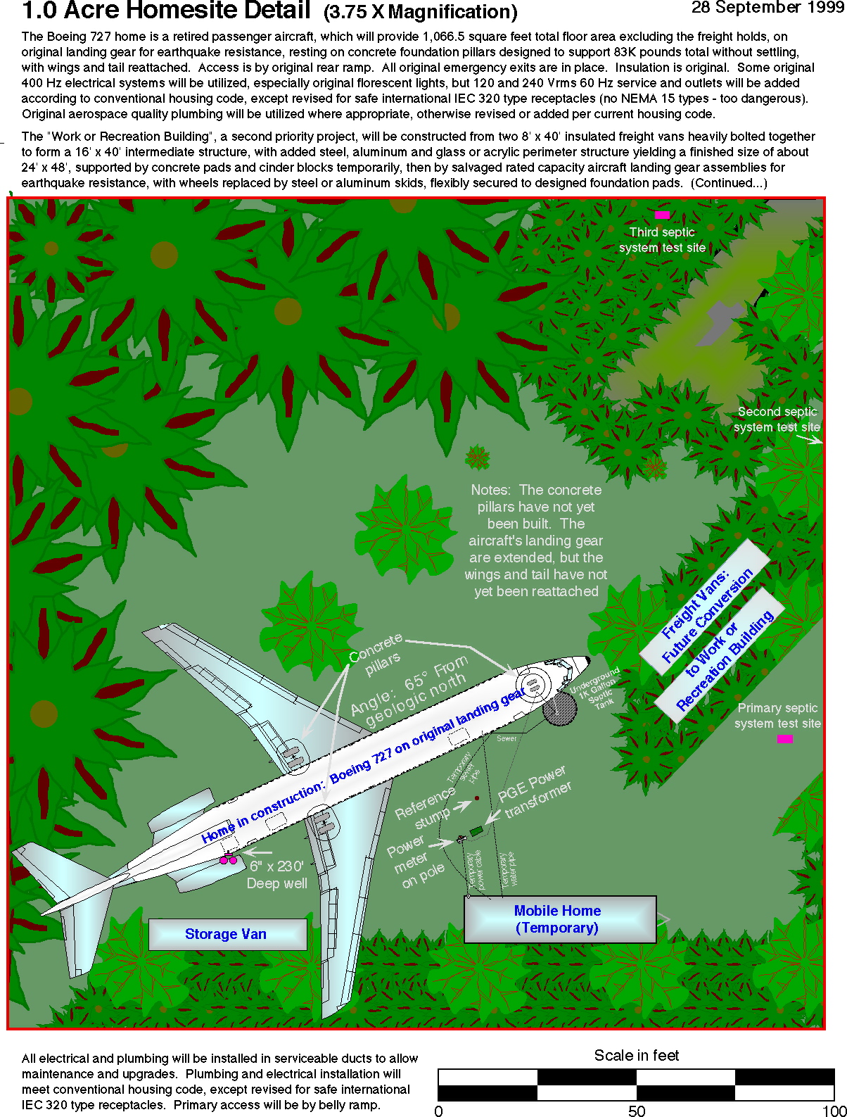