
1.5 MB

1.7 MB

1.6 MB

1.8 MB

1.6 MB

1.7 MB

1.6 MB

1.6 MB

1.6 MB
1.6 MB

1.7 MB
Tail Disassembly
18 January 2003:
Click on a thumbnail for the full size image. File sizes approximately as shown - they're large, high resolution images.
The first four are external horizontal cut line images. The rest are forward spar images. I'll try to add images of bulkhead cuts and other items, time permitting.
Procedure:
Key factors for efficient and minimally
destructive tail removal include: Establishing a proper outer skin and internal
bulkheads cut line, staggering the front spar cut, and nondestructive removal
of the two rear spar brackets, the number two engine nacelle and related
assemblies, and the upper half of the S duct. The lower half of the S duct
need not and should not be removed unless it's desired to clear the interior
of the tail area for some reason that's unrelated to disassembly and moving
of the aircraft - the lower half of the S duct doesn't impede disassembly
work or increase the size of the aircraft for overland moving. If it is
decided to remove the lower half of the S duct, it will have to be destructively
cut to do so.
All cut-off saw work should be performed with the thinnest cutting wheels that can safely handle each task.
The following work should be accomplished in the order described.
The number two engine nacelle assembly consists of the nacelle, a composite forward S duct cover, a metal inverted U shaped junction bracket, and some associated small air ducts. It should be nondestructively removed by removing it's numerous attachment bolts and separating the small duct junctions, some of each of which are accessed through service panels, then lifting it off with a small crane (it's quite light).
The two halves of the S duct should be separated by removing all the perimeter junction bolts at the midpoint of the S duct. Some of the bolts are in very restricted areas and require a very thin person (I can just barely do it, and I weigh only 123 pounds). The upper portion of the S duct can then be finessed out from the top, where the number two engine nacelle used to be, and off of the aircraft with a small crane. The lower section of the S duct should be left in place.
Numerous stainless steel control cables and titanium ducts should be separated at whichever junctions are closest to the cut line described below so that they will allow the tail to be pulled free later. The junction connectors of the control cables will not feed through some of the cable's guide wheels, so one must select disconnect locations carefully so that the cables will be genuinely free to separate later. A wiring harness just forward of the heavy forward spar on the aircraft's right side will have to be destructively cut - there are no nearby connectors. Each wire has it's own frequently repeated printed serial number, so they can be identified and spliced back together later rather easily.
For the following work, a medium crane must be rigged to hold the tail so that it can't topple, and secured with enough upward tension to just counter the weight of the tail, as best can be judged. All persons must remain aware of the possibility of sudden and unpredictable tail movement, including horizontal shifts, and maintain as safe a position as possible as they work.
The skin cut line should be from just above the bottom of the rudder hinge line as shown in the images below, progressing exactly horizontally forward to the number two engine nacelle assembly. It can be easily cut with abrasion wheel type cut-off saws from the outside, except that the ribs require finishing cuts from the inside due to their width as shown in the forth image, also easy. The cut must avoid the rear tail spar brackets at the bottom of the rudder (first image) - it's not necessary to cut down to those brackets, and they mustn't be damaged.
The internal rear bulkheads that connect above and below the cut line from left to right (side to side) must be cut with compact cut-off saws from the inside. They cut easily and quickly, but access to the rear bulkheads is very restricted - a small and agile person is required (I cut all the internal tail bulkheads on my aircraft, and can do so again). Both straight and right angle compact cut-off saws are needed. Access starts from within the internal service tunnel.
Secure the tail with rigging to prevent side to side motion before performing the following steps.
The rear brackets should be freed by removing their connecting bolts. There are four bolts for each of the two brackets, two on the bottom and two on the side. Removal is a two person job, with one small person on the inside of the tail and the other on the outside (to pull the side bolts free as they're pushed or tapped partially out from the inside).
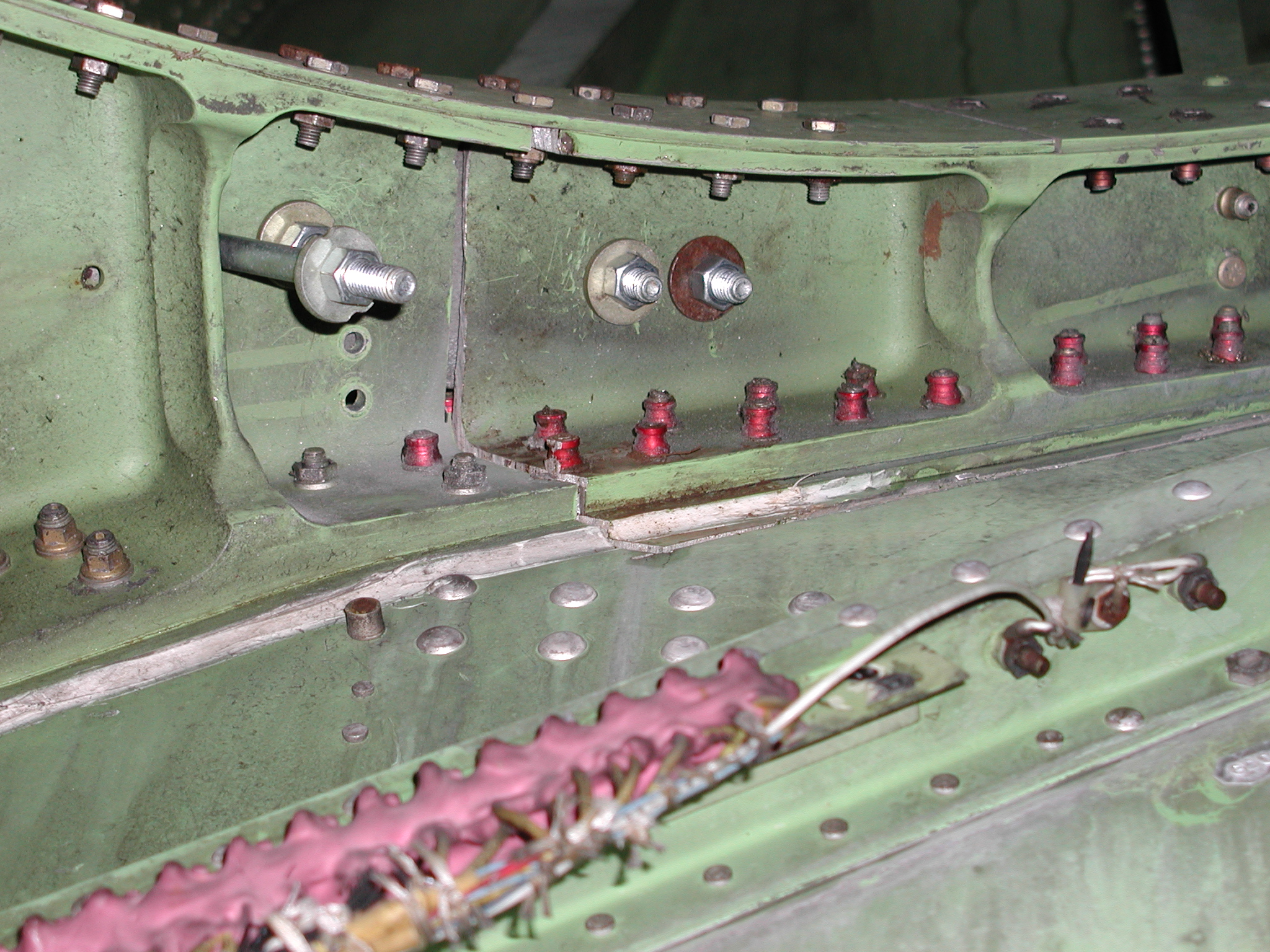
This is important: The forward spar consists of a heavy custom shaped cast spar and a relatively thin inner curved laminate plate that's secured to the cast spar with numerous bolts. These must be cut, but with a significant stagger rather than at the same location - this is critical for reassembly. The bolts should be removed from where the laminate plate will be cut down to a point well below the cast spar cut line. The laminate plate should then be cut about a foot or more above the cut line selected for the heavy cast spar, being very careful to avoid damage to the heavy cast spar. (The stagger distance should be greater than was selected on my aircraft.) The laminate plate should then be pulled back from the heavy cast spar with a turnbuckle and chain or other pulling tool. The heavy cast spar should then be cut with a cut-off saw, with, as usual, as thin a cut as possible. Be careful - as the spar cut nears completion, the tail will become free, lurching in response to the lifting force of the crane. Once the heavy cast spar cut is complete release the tools holding the laminate plate.
The tail should now be free to be pulled off with the crane. This should be done carefully of course, pulling straight up so as to avoid any damage, with particular attention to the rear tail brackets. Watch for control cables or other structure which may not have been completely freed.
If the tail was removed in one assembly with both vertical and horizontal stabilizer intact, it will be necessary to remove the composite trailing fairing before it can be set on the ground - otherwise the weight of the tail will crush the fairing. The fairing is easy to remove via it's perimeter connection bolts. The tail can then be safely placed on the ground, tilted with one end of the horizontal stabilizer resting on the ground.
1.5 MB |
1.7 MB |
1.6 MB |
1.8 MB |
1.6 MB |
1.7 MB |
1.6 MB |
1.6 MB |
1.6 MB |
1.6 MB |
1.7 MB |
|
Bruce Campbell
15270 SW Holly Hill Road
Hillsboro, OR 97123-9074
Voice: 503-628-2936 (Pacific)
Cell: 503-957-0727. (Critical requirements only, costs $1 per minute)
![]() Note: UCE (spam) email or any email
distributed on an "opt out" basis is absolutely prohibited. Do
not send any such email to this address.
Note: UCE (spam) email or any email
distributed on an "opt out" basis is absolutely prohibited. Do
not send any such email to this address.